Well, THAT's Not Gonna Fucking Work!

Re: Well, THAT's Not Gonna Fucking Work!

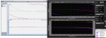
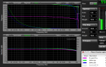
Let me reply to my reply. I guess I just assumed unbalanced. Probably not, but the amount of noise I'm guessing that is present above 2k suggested it. The two phase lines start out about 120deg out of phase. Their slopes seem pretty near equal thus their total "delay" is equal. At the beginning the green high output is descending quicker. There could possibly be some DC blocking stuff in the dbx for the high output? I would measure all three channels simultaneously with a piece of software which doesn't use noise as a stimulus and compare.

On another note, I agree that the Xilica XP/XD products function well for their price. I have measured them extensively with my software, not SMAART, and never seen anything like what your picture shows above.


+1 "There could possibly be some DC blocking stuff in the dbx for the high output? I would measure all three channels simultaneously with a piece of software which doesn't use noise as a stimulus and compare."
 
Re: Well, THAT's Not Gonna Fucking Work!

+1 "There could possibly be some DC blocking stuff in the dbx for the high output? I would measure all three channels simultaneously with a piece of software which doesn't use noise as a stimulus and compare."

I think y'alls are missing the point. Through to through with no filtering or other processing the box in to out should look more like the ref trace. Don't agree with the data? That's what peer review is all about. Shoot some traces and show us what you have.

A couple of other points...

Smaart doesn't have to use noise as a stimulus. In the early years if was possible to piss Sam off using just noise. (and I loved doing it...) If Benny uses music he's going to get the same results. At the point in the test, this isn't the "high output". It's a full range output. There shouldn't be that difference in the results. Think different? Do the tests, show your math and make the case.
 
Re: Well, THAT's Not Gonna Fucking Work!

+1 "There could possibly be some DC blocking stuff in the dbx for the high output?

Peter,

You're an EE, so you don't get a pass on supporting this one. Plus you can't throw rocks at me from Australia :lol:

If the effect in the trace was a consequence of DC blocking capacitors, it would show up in the magnitude response, as the RC conjugate of a DC blocking capacitor+build out resistor is a minimum phase system. Both channels exhibit substantial LF phase shift without the corresponding magnitude shift. There's some non minimum phase funny business here. It could be in the dsp, but it seems more likely to be in the analog bits or AD/DA.

The high frequency effects near Nyquist are going to be a consequence of how the DSP handles bilinear Z math. The polarity inversion is anybody's guess.
 
Re: Well, THAT's Not Gonna Fucking Work!

Peter,

You're an EE, so you don't get a pass on supporting this one. Plus you can't throw rocks at me from Australia :lol:

If the effect in the trace was a consequence of DC blocking capacitors, it would show up in the magnitude response, as the RC conjugate of a DC blocking capacitor+build out resistor is a minimum phase system. Both channels exhibit substantial LF phase shift without the corresponding magnitude shift. There's some non minimum phase funny business here. It could be in the dsp, but it seems more likely to be in the analog bits or AD/DA.

The high frequency effects near Nyquist are going to be a consequence of how the DSP handles bilinear Z math. The polarity inversion is anybody's guess.


No rocks from OZ Phil … :razz:

To look at things from another perspective, I would be surprised if DBX got it that wrong, they may have, but I would measure it again with some caution and eliminate every possible error.

It’s just sooo scary if they did … I expect something strange is happening. I don’t disagree with your comments and I’m not real sure what’s happening ... its very strange.
As you said” it seems more likely to be in the analog bits” … Caps ???

l will send you a PM when I have time.

Peter

PS sorry about the mess above .. fire wall issues

 
Last edited:
Re: Well, THAT's Not Gonna Fucking Work!

The apparent polarity inversion is troubling. Not questioning Bennett's measurement capability, he knows what he's doing, but I'd double check the cables & the settings in the DSP. I've had things like this bite me in the backside before.

The reason I suspect the DSP settings is there seems to be a different propagation time (latency) through the DSP for the LOW output (purple) & HIGH output (green). Even though there is no impulse response shown the different slopes of the phase response curves are indicative of this. If the arrival time of the test signal was the same from the LOW and the HIGH outputs the phase traces would have the same slope in the high frequency region.

There may also be other causes for this behavior. Just a thought.
 
I'd double check the cables & the settings in the DSP. I've had things like this bite me in the backside before.

Charlie,

That's why I provided the hard cabled trace of my measurement interface. Single sample delay changes will not make the two slopes line up (ignoring the apparent polarity reverse), their HF behavior is not the same above 4K or so. The program in the DRPA+ is blank, and I went through it manually and verified that every delay, EQ, etc. was off after rolling all the crossover filters out.
 
Re: Well, THAT's Not Gonna Fucking Work!

Sounds to me like a faulty/damaged output channel on the DRPA+. Did you move the leads from the one trace to another to rule everything else out? Do any of the other DRPA+ output channels exhibit this behavior? Maybe this calls for more of these units to be investigated... (see whether or not it is just a faulty unit)
 
Re: Well, THAT's Not Gonna Fucking Work!

The program in the DRPA+ is blank, and I went through it manually and verified that every delay, EQ, etc. was off after rolling all the crossover filters out.

Have you tried programming this differently, just to see if that phase shift is still there with different digital crossover settings? (I know...you shouldn't have to do this)
 
Re: Well, THAT's Not Gonna Fucking Work!

Did you plug in another DSP, or crossover and get a measurement that didn't make the phase go crosseyed?
 
Re: Well, THAT's Not Gonna Fucking Work!

P.S. Smaart thinks the delay on both should be one sample more, i.e. 0.75msec, but I liked one sample less. In neither case does the HF phase flatten out as one would expect.
Just tested one of my DriveRackPa units out.

It inverts polarity for LF, MF, and HF from input to output, as with your interface, the phase line with a hard wire is basically flat, but in the case of the DRPA, all the outputs are about 180 degrees off.

Smaart AutoSM sets latency as 1.52ms for LF, 1.50ms for HF.
Latency in three way mode is 1.52ms for LF, MF, and 1.50ms HF.

The LF and MF traces look identical.

Smaart latency increments (.02ms) are not small enough to flatten the phase trace out, my M-Audio interface trace, the purple one that shows about -34 at 16K, flips to +120 when .02 is added as a delay.

Using the Mac in /out, no interface still resulted in a HF phase drift, though IIRC not quite as much as with the M-Audio. Andy (on the old LAB) verified that with a straight wire in/out with his Mac too.

The difference between the Low/Mid/High phase trace on the DRPA seem to be the result of a tiny delay range difference, unlike your DRPA +, which looks hosed.

This was a learning experience for me, I was unaware all the DRPA outputs were inverted, and I had never realized that the filters still affected phase even when switched “out”.

I don’t know what DBX did in the “+” version to (re) invert the HF (making it “sorta normal”), perhaps they threw in a few filter caps to eliminate the “shotgun” sound the DRPA made when power is lost when it is still in use, the funky HF phase response looks kind of like some (bad) passive filter.

That said, as Phil said “If the effect in the trace was a consequence of DC blocking capacitors, it would show up in the magnitude response”, and the magnitude response looks good. If they can't get the in/out polarity correct, who knows what else they can mess up.

As an aside, I had to invert the polarity on my HF drivers when I was using DC protection caps on the HF drivers in my system, when I eliminated them polarity went back to normal, and delay time matched the physical path length difference more closely.

Well, back to my electric boat project (using the Electric Paddle, more than 3 dB more efficient and faster than trolling motors) where I only have to worry about battery polarity, not phase...

Art
 

Attachments

  • DRPA and +.png
    DRPA and +.png
    167.2 KB · Views: 2
Re: Well, THAT's Not Gonna Fucking Work!

So my question is what crossover types/slopes did you have it set for. I am assuming that you had both the lows and the highs set so that both would reproduce the entire bandwidth but....
Did you change crossover types/slopes and re-measure. It sounds to me like maybe, just maybe, DBX figures that on an entry level DSP that they need to flip the polarity for one bandwidth to the next based upon the type/slope. Did you have this set as LR-24 for both the HPF of the highs and LPF of the lows?

I could be ASSuming out my ass but it would be nice to know.
Can't speak for the DRPA +, but the upper phase traces all were similar on the Drive Rack PA regardless of filter type, but the LF phase bottom end trace "upward curve" change with filter type, even when the filters are set to "out".

The picture below shows the difference between two "out" filters, I forgot to label them, but IIRC they were 24 and 12 BW.

Since there is no polarity switch available, I'd doubt any polarity switching is intentional in these devices.

Art
 

Attachments

  • DRPA.png
    DRPA.png
    122.4 KB · Views: 0
Re: Well, THAT's Not Gonna Fucking Work!

Never measured a PA or 260 so I can't comment on what is being found. I do know they have presets for different speaker types. I wonder even if all the settings are changed to flat if still these different speaker types are still in place. The "wizzard" is set up for say a JBL speaker. The given speaker type requires the Lows and Highs to be out of polarity from the mids? Did anyone check the wizzard and see if it was still set up for a given speaker?

Douglas R. Allen
 
Sounds to me like a faulty/damaged output channel on the DRPA+. Did you move the leads from the one trace to another to rule everything else out? Do any of the other DRPA+ output channels exhibit this behavior? Maybe this calls for more of these units to be investigated... (see whether or not it is just a faulty unit)

I tested both L and R in to both L and R LOW and HIGH outs with the unit in two way stereo mode. I haven't gone any further than that since discovering this unit was useless for creating traces for class... Of course I plan on keeping it around for new slides for the AES DSP panel, and the talk I'm giving at the Parson's expo in just a few weeks, since it's perfect for that.
 
Re: Well, THAT's Not Gonna Fucking Work!

No rocks from OZ Phil … :razz:

To look at things from another perspective, I would be surprised if DBX got it that wrong, they may have, but I would measure it again with some caution and eliminate every possible error.

It’s just sooo scary if they did … I expect something strange is happening. I don’t disagree with your comments and I’m not real sure what’s happening ... its very strange.
As you said” it seems more likely to be in the analog bits” … Caps ???

l will send you a PM when I have time.

Peter

PS sorry about the mess above .. fire wall issues


I couldn’t finish my post last night with out the fire wall interrupting. At 8:30pm the router’s fire wall rules block the social network sites to keep the kids focused on home work…but for some reason it thought that Phil Graham was a social networking site and Bennett was a porn site … go figure!

Anyway to add a bit more … one of my immediate reactions was to go measure it again with different test gear, e.g. have a look at it with a multi channel oscilloscope, look for distortion at various signal levels, square wave response and the relative phase between signals etc. It may tell you a bit more about what’s going on. If nothing else, it will eliminate a few possibilities.

There are a lot of functions in the drive rack that could impact on the output traces - Feedback Elimination, GEQ, Compressor, Limiters, Sub-harmonic Synthesizer as well as crossovers, who know want these are doing and if they are lurking in the background.

Its also interesting to note that according to dBX the the HF output is created using a HP filter. The Mid and Low outputs are created using BP filters consisting of Low-Pass and High-Pass filters.
 
Last edited:
Re: Well, THAT's Not Gonna Fucking Work!

Peter,

You're an EE, so you don't get a pass on supporting this one. Plus you can't throw rocks at me from Australia :lol:

If the effect in the trace was a consequence of DC blocking capacitors, it would show up in the magnitude response, as the RC conjugate of a DC blocking capacitor+build out resistor is a minimum phase system. Both channels exhibit substantial LF phase shift without the corresponding magnitude shift. There's some non minimum phase funny business here. It could be in the dsp, but it seems more likely to be in the analog bits or AD/DA.

The high frequency effects near Nyquist are going to be a consequence of how the DSP handles bilinear Z math. The polarity inversion is anybody's guess.

Commonly a forth order filter will be used for dc blocking. I haven't seen a measurement below 20 Hz yet. See attached jpeg. Sorry I just plotted the digital IIR filter not an actual active one.
 

Attachments

  • hpfilter for dc blocking.jpg
    hpfilter for dc blocking.jpg
    85.3 KB · Views: 1
Re: Well, THAT's Not Gonna Fucking Work!

I think y'alls are missing the point. Through to through with no filtering or other processing the box in to out should look more like the ref trace. Don't agree with the data? That's what peer review is all about. Shoot some traces and show us what you have.

A couple of other points...

Smaart doesn't have to use noise as a stimulus. In the early years if was possible to piss Sam off using just noise. (and I loved doing it...) If Benny uses music he's going to get the same results. At the point in the test, this isn't the "high output". It's a full range output. There shouldn't be that difference in the results. Think different? Do the tests, show your math and make the case.

Mark got spanked by Dave Stevens ... that's considered a compliment around here !

w/r
 
Re: Well, THAT's Not Gonna Fucking Work!


Anyway to add a bit more … one of my immediate reactions was to go measure it again with different test gear, e.g. have a look at it with a multi channel oscilloscope, look for distortion at various signal levels, square wave response and the relative phase between signals etc. It may tell you a bit more about what’s going on. If nothing else, it will eliminate a few possibilities.

There are a lot of functions in the drive rack that could impact on the output traces - Feedback Elimination, GEQ, Compressor, Limiters, Sub-harmonic Synthesizer as well as crossovers, who know want these are doing and if they are lurking in the background.

Its also interesting to note that according to dBX the the HF output is created using a HP filter. The Mid and Low outputs are created using BP filters consisting of Low-Pass and High-Pass filters.

After consulting the dbx website I noticed that the outputs contain an RF filter. It is possible that a poor choice of notching filter has a phase response showing up.
Also, L*C for a notching filter with phase deviation starting at 16kHz is around 100x10-12. dbx could have chose some poor output topology which when attached to a high impedance measurement system causes the problem. The problem may not be visible when connected to a 600Ohm or even 10kOhm input, but a 1MOhm input might make the Q small enough to bring the the phase change into the audio spectrum.

Or maybe its always a problem. Who knows. I just wanted to know why you guys were seeing this behavior.