New DIY Mid High (90deg) - AKA PM90

Hi Chris,

Yes I think they would work – The SIM shows it’s not quite as smooth as the RCF, but with a fraction more SPL.
Before you build this design, it was designed to be used with DSP correction to get a flat response. The HF driver must be able to operate down to 600-700Hz. The design will not work if you cross higher than this. I think the BMS 4594 / 4594HE is probably the best solution.
 
Chris, be sure to verify that there is sufficient space between the 12" drivers for the high driver: the BMS driver just fits between the RCF drivers and the Beymas look as if they provide a little less space between the 'spokes' (is that the right word?).
 
Chris, be sure to verify that there is sufficient space between the 12" drivers for the high driver: the BMS driver just fits between the RCF drivers and the Beymas look as if they provide a little less space between the 'spokes' (is that the right word?).

I haven't modeled it to be sure, but it's shorter than the B&C 12NDL76s which I've been using, and the VC is the part the BMS likes to collide with first, so there should be no issues with clearance assuming Chris is using the drawings I've posted.
 
This MID-HIGH looks incredible!

Are the final build specs posted on this thread, I did not see them as I was glancing around?

Just anyone have a suggested on a sweet set of ampa setup they have used to power these beauties?

Wonderful!

Evan
 
This MID-HIGH looks incredible!

Are the final build specs posted on this thread, I did not see them as I was glancing around?

Just anyone have a suggested on a sweet set of ampa setup they have used to power these beauties?

Wonderful!

Evan

There are some final plans (pdf format and dwg), in terms of amps I'm using Powersoft K series. Some people have use the K series processing as well.

https://www.dropbox.com/s/h16is6mbji...rrent.pdf?dl=0
https://www.dropbox.com/s/xiuyecjy9k...rrent.dwg?dl=0
 
Hey Peter and soundforum. i am currently trying decide on a midtop cab to go above 4hogs and 2 2x15" flh kickbins. current plan for 1 stack only - possibly add tweeters above the midtop cabs in the future.

are there any apple-to-apple comparisons between this PM design and say: MT121, SMT122 or the MT130? or even a direct radiator

Lots of opinions online so hard for a noob to navigate... From my research i had thought the MT121 would be the most suitable for my application because:
1. my FLH xover is ~200-250hz - where this PM design goes quite low so some wasted bandpass.
2. i prefer a single 12" and single horn per cabinet for weight concerns and to keep the stack at a manageable height. presume this PM design cant be built with just a single 12" mid?
3. if the above is correct - i figure building four mt121s would be best - and since our shows are 150-300 capacity, the poor dispersion and long throw of the mt121 can be mitigated by just having more and not running them so hard - which should be fine since there will be the odd time i split the full stack into two-halfs depending on room shape.

does my logic make sense here? would really appreciate the input! thanks!

Hi.

The PM90/60 was designed to produce the most SPL and sound quality possible for a pole mounted speaker. It was designed to go down to 100 Hz so that it could be flown and not sound like there was a gap between the tops and a ground stack sub. Getting good output down to 100 Hz and keeping the size and weight down is the tricky bit.

In your application I would probably use something else. The PM90/60 does not have flat raw frequency response and is designed to be run with DSP processing. The mid horn is bent so there is a limit to how high it can be crossed over. As a result the HF driver has to work quite hard. This was the reason for selecting the BMS 4594 – it is designed to go low.

This design cannot be built with one driver. If you only need to go from 200-250Hz up you can use a "straight" horn and cross over to the HF driver at a higher frequency. This gives you a lot more cost effective options when selecting a HF driver, I would check out B&C’s new DE1090TN.
 
Last edited:
In your application I would probably use something else. The PM90/60 does not have flat raw frequency response and is designed to be run with DSP processing. The mid horn is bent so there is a limit to how high it can be crossed over. As a result the HF driver has to work quite hard. This was the reason for selecting the BMS 4594 – it is designed to go low.

Peter,

I have no intention of hijacking your thread, but my design is a derivative of your PM90, so I thought I would thank you here for the design ideas. I couldn't justify spending $2500 on drivers, so I made a bit less capable (130 dB continuous), but lighter (about 42 lb) and less expensive ($1000/pair) version with a single 12" B&C 12NDL76 and Eminence N314T. I managed to get pretty reasonable response to 1000 Hz from the mid, so I could use a less capable compression driver.

The MTM90 is described in detail at diyAudio.

Thanks again.

Marc
 

Attachments

  • 2 stacks at BBB.jpg
    2 stacks at BBB.jpg
    62.9 KB · Views: 235
Peter,

I have no intention of hijacking your thread, but my design is a derivative of your PM90, so I thought I would thank you here for the design ideas. I couldn't justify spending $2500 on drivers, so I made a bit less capable (130 dB continuous), but lighter (about 42 lb) and less expensive ($1000/pair) version with a single 12" B&C 12NDL76 and Eminence N314T. I managed to get pretty reasonable response to 1000 Hz from the mid, so I could use a less capable compression driver.

The MTM90 is described in detail at diyAudio.

Thanks again.

Marc

Hi Marc,

It’s great to see other people experiment with this dipole configuration and being able to reproduce a square waves.

By using one driver you will not lose any efficiently, just power handling. The disadvantage with one driver is the depth of the box – it has to be deep enough to accommodate the HF horn and the LF driver.

The advantage using the BMS compression driver with the HF950 horn was being able to crossover low enough to stop the vertical pattern collapsing around 650 Hz.

Here is a SIM of the vertical directivity. Although there are a few compromises with what I have done with the SIM, it does show what happens if you crossover higher (it matches what you have measured in you DIYaudio post) with a 20 dB dip off axis (vertical) around 650 Hz.

I have been thinking about doing a simpler version of the PM90 using a B&C DE1090TN - it will be cheaper, smaller, lighter have better pattern control ...BUT ... not as loud.
 

Attachments

  • Vertical directivity.jpg
    Vertical directivity.jpg
    150.8 KB · Views: 99
Peter,

I have no intention of hijacking your thread, but my design is a derivative of your PM90, so I thought I would thank you here for the design ideas. I couldn't justify spending $2500 on drivers, so I made a bit less capable (130 dB continuous), but lighter (about 42 lb) and less expensive ($1000/pair) version with a single 12" B&C 12NDL76 and Eminence N314T. I managed to get pretty reasonable response to 1000 Hz from the mid, so I could use a less capable compression driver.

The MTM90 is described in detail at diyAudio.

Thanks again.

Marc

Hi Marc,
It’s great to see other people experiment with this dipole configuration and being able to reproduce a square wave.

By using one driver you will not lose any efficiently, just power handling. The disadvantage with one driver is the depth of the box – it has to be deep enough to accommodate the HF horn and the LF driver.

The advantage using the BMS compression driver with the HF950 horn was being able to crossover low enough to stop the vertical pattern collapsing around 650 Hz.

Here is a SIM of the vertical directivity. Although there are a few compromises with what I have done with the SIM, it does show what happens if you crossover higher (it matches what you have measured in your DIYaudio post) with a 20 dB dip off axis (vertical) around 650 Hz.

FWIW I have been thinking about doing a simpler version of the double12 – it will be cheaper to build, use a B&C DE1090TN compression driver, smaller, lighter, better vertical pattern control … BUT … not as loud.
 

Attachments

  • Vertical directivity.jpg
    Vertical directivity.jpg
    150.8 KB · Views: 12
Peter,

I have no intention of hijacking your thread, but my design is a derivative of your PM90, so I thought I would thank you here for the design ideas. I couldn't justify spending $2500 on drivers, so I made a bit less capable (130 dB continuous), but lighter (about 42 lb) and less expensive ($1000/pair) version with a single 12" B&C 12NDL76 and Eminence N314T. I managed to get pretty reasonable response to 1000 Hz from the mid, so I could use a less capable compression driver.

The MTM90 is described in detail at diyAudio.

Thanks again.

Marc

Hi Marc,

It’s great to see other people experiment with this dipole configuration and being able to reproduce a square wave.

By using one driver you will not lose any efficiently, just power handling. The disadvantage with one driver is the depth of the box – it has to be deep enough to accommodate the HF horn and the LF driver.

The advantage using the BMS compression driver with the HF950 horn was being able to crossover low enough to stop the vertical pattern collapsing around 650 Hz.

Here is a SIM of the vertical directivity. Although there are a few compromises with what I have done with the SIM, it does show what happens if you crossover higher (it matches what you have measured in your DIYaudio post) with a 20 dB dip off axis (vertical) around 650 Hz.

FWIW I have been thinking about doing a simpler version of the double12 – it will be cheaper to build, use a B&C DE1090TN compression driver, smaller, lighter, better vertical pattern control … BUT … not as loud.
 

Attachments

  • Vertical directivity.jpg
    Vertical directivity.jpg
    150.8 KB · Views: 8
Peter,

I have no intention of hijacking your thread, but my design is a derivative of your PM90, so I thought I would thank you here for the design ideas. I couldn't justify spending $2500 on drivers, so I made a bit less capable (130 dB continuous), but lighter (about 42 lb) and less expensive ($1000/pair) version with a single 12" B&C 12NDL76 and Eminence N314T. I managed to get pretty reasonable response to 1000 Hz from the mid, so I could use a less capable compression driver.

The MTM90 is described in detail at diyAudio.

Thanks again.

Marc

Hi Marc,

It’s great to see other people experiment with this dipole configuration and being able to reproduce a square wave.

By using one driver you will not lose any efficiently, just power handling. The disadvantage with one driver is the depth of the box – it has to be deep enough to accommodate the HF horn and the LF driver.

The advantage using the BMS compression driver with the HF950 horn was being able to crossover low enough to stop the vertical pattern collapsing around 650 Hz.

Here is a SIM of the vertical directivity. Although there are a few compromises with what I have done with the SIM, it does show what happens if you crossover higher (it matches what you have measured in your DIYaudio post) with a 20 dB dip off axis (vertical) around 650 Hz.

FWIW I have been thinking about doing a simpler version of the double12 – it will be cheaper to build, use a B&C DE1090TN compression driver, smaller, lighter, better vertical pattern control … BUT … not as loud.


Attachments

  • Vertical directivity.jpg
    Vertical directivity.jpg
    150.8 KB · Views: 13
Peter,

I have no intention of hijacking your thread, but my design is a derivative of your PM90, so I thought I would thank you here for the design ideas. I couldn't justify spending $2500 on drivers, so I made a bit less capable (130 dB continuous), but lighter (about 42 lb) and less expensive ($1000/pair) version with a single 12" B&C 12NDL76 and Eminence N314T. I managed to get pretty reasonable response to 1000 Hz from the mid, so I could use a less capable compression driver.

The MTM90 is described in detail at diyAudio.

Thanks again.

Marc

Hi Marc,

It’s great to see other people experiment with this dipole configuration and being able to reproduce a square wave.

By using one driver you will not lose any efficiently, just power handling. The disadvantage with one driver is the depth of the box – it has to be deep enough to accommodate the HF horn and the LF driver.

The advantage using the BMS compression driver with the HF950 horn was being able to crossover low enough to stop the vertical pattern collapsing around 650 Hz.

Here is a SIM of the vertical directivity. Although there are a few compromises with what I have done with the SIM, it does show what happens if you crossover higher (it matches what you have measured in your DIYaudio post) with a 20 dB dip off axis (vertical) around 650 Hz.

FWIW I have been thinking about doing a simpler version of the double12 – it will be cheaper to build, use a B&C DE1090TN compression driver, smaller, lighter, better vertical pattern control … BUT … not as loud.
 

Attachments

  • Vertical directivity.jpg
    Vertical directivity.jpg
    150.8 KB · Views: 14
FWIW I have been thinking about doing a simpler version of the double12 – it will be cheaper to build, use a B&C DE1090TN compression driver, smaller, lighter, better vertical pattern control … BUT … not as loud.

Hi Peter,
I am looking forward to it. How about double 10" of the same design? This will shed the weight a great deal I think.
 
Peter,

I'd absolutely love to take a look at any ideas you've had for simplifying the box. I've spent a lot of time thinking on how to build the previous version, and might have some insight as far as cost/weight/time savings.

Also, what software do you use for your sims? I've been wondering for a few years now.

Hlep - On a similar vein, I've been planning on doing a double 10" and horn MTM design for a while now. I'll let you know if I ever get around to it.

Best.

The idea is to build a double 10 or 12 inch version of this design below using RCF HF950 horn. The problem with using a 10" driver in the PM90/60 horn is the box ends up being more or less the same size and you cant really increase the crossover frequency to accommodate standard compression drivers.

The problem with a normal MTM design is controlling the vertical directivity, the double 14 prototype below behaves almost perfectly.

The software I used was Ray End .... I think Danley have bought it.
 

Attachments

  • double 14-1.jpg
    double 14-1.jpg
    32.8 KB · Views: 213
Last edited:
Hi guys,
Peter, thank you for the inspiration starting of this journey of designing a derivative based on yours and some of my own findings/research.
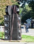
I've designed a version using two 15" (15NW76) in a sealed enclosure with the drivers facing the end panels through a short horn like adapter.
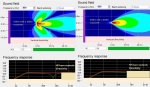
[FONT=&amp]I find it imperative to reduce the vertical source size in a MTM. Assuming we have DSP at our disposal, the sealed alignment using two large radiators with good excursion capabilities yields quite good low frequency efficiency (not unprocessed sensitivity though!). It is capable of 135db max spl down to 80hz 24dbLR, when applied eq, which is around the limit of the high frequency driver anyway. It's displacement limited, so those 135dB does not pull lots of power causing power compression and overheating. Unlike, the vented alignment having port noise and very delicate rear volume requirements, the LF output of the sealed alignment decreases at 12db/octave and can be adjusted as low as reasonable as long as one keeps an eye on the excursion below natural cutoff.[/FONT]

Link to Don B. Keele's paper (part 1) on Linear phase crossovers and symmetric driver arrays (see MTM):
http://www.xlrtechs.com/dbkeele.com/PDF/Keele%20(2007-09%20AES%20Preprint)-%20Linear%20Phase%20Digital%20Crossover%20Flters%20Part%201.pdf

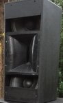
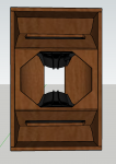
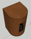
Here is a sketchup pic. The large cutout in the rear panel is to accommodate an amp module. The entire side and rear is made from a single piece of kerfed 18mm birch ply, to approach a cylindrical enclosure for good damping and minimized wall flex. The front panel is removable to access the 15"s and to allow different HF horn/driver combinations

I too considered every imaginable layout possible and ultimately arrived at this fairly simpel one. There is a lot of ways do such a speaker but only a few designs seems to obtain a good balance of requirements. This is just me trying to make anyone who is looking into designing their own version, avoid being blinded by a single design or idea
Best regards Fred
 

Attachments

  • Untitled picture.png
    Untitled picture.png
    259.8 KB · Views: 159
  • Untitled picture 2.png
    Untitled picture 2.png
    368.9 KB · Views: 147