Help with EAW SM122's.

Marsellus Fariss

Sophomore
Oct 25, 2011
121
1
0
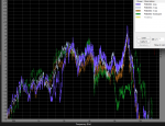
So we bought some EAW SM122's last year. And they weren't in the best shape. I've been into all of them cleaning out some very dirty HF coil slots, replacing a diaphram or two and one HF magnet assembly as the phase plug had the center portion missing. Still after all the work and fresh parts they have problems. Here's SMAART traces of all 4 with nothing but HPF applied.

SM122.JPG

As you can see they very but the purple trace (#4) is very different.

Since I've been inside them all and checked for aftermarket and rubbing drivers and can eliminate that as an issue I can only think of the passive crossovers as the problem.

They have a interesting passive crossover network with a midrange control that goes from -6 to +3. These controls in there current condition don't appear to work except when you turn them past 0 to the (+) side of things then you get the mid range boost to engage but only at one level. Not variable as you turn the knob. On a few of the wedges you need set this control to engage the boost to get the wedge to behave appropriately and on a few you need to have it off to get them close to parity.

What should I look at on the crossover networks to get these to behave? Caps? The first three I can live with as the sonic differences aren't that great but #4 sounds obviously different. I have a note on the worst wedge itself as to how to bring it back to earth with graphic EQ settings but this is not how I like to roll.

I don't mind digging into them to replace parts on the crossover PCB's but I need to know what's going to help and what's wasting time. I've already wasted enough time on these.

Thanks guys.


Edit: I should add that it's not possible to just bypass the crossovers and bi-amp as we don't have the amp channels and NL4 and buying such would be more expensive then just selling them off for something else.
 
Re: Help with EAW SM122's.

So we bought some EAW SM122's last year....

Marsellus,

It is pretty hard to say anything concrete with such a smoothed SMAART curve. Especially for controlled shop measurements, 1/24th smoothing for the Magnitude, and 1/12 smoothing for the phase is plenty. I'll typically use unsmoothed mag and 1/24 phase smoothing during design, and 1/48 mag smoothing during voicing.

It would appear that you have a level problem, as Rob mentions, Also, it would appear that might have a polarity inversion at the HF XO point. It is hard to say with 100% certainty, given the amount of smoothing, but if the null was much deeper when viewed without smoothing, then that would indicate more clearly the possibility of a polarity inversion.

It is possible that EAW intentionally left the polarity "incorrect" to maximize the null in a region where feedback was an issue, but that seems unlikely. It is also possible that this dip is merely a design feature of the crossover. Again it is hard to say definitively with so much smoothing.

Can you map out the passive XO schematic and post it? That would be most revealing, and help figure out what is going on and where to proceed.
 
Last edited:
Re: Help with EAW SM122's.

Marsellus,

The response differences look more like driver than crossover differences.
The original spec is +/- 3 dB 80-18 kHz, your monitors range about +/- 5 dB worst case.
For old (cheap) drivers, another couple dB off is not unusual.
I have four monitors with old drivers with similar differences as yours, and I built the crossovers with new parts.
When building the crossovers, I had considered making individual part adjustments to compensate for the driver differences, but decided against it, as diaphragm replacement would change the response again, and the "old style" diaphragms in 3 of the 4 monitors are no longer available..

I just numbered the cabinets, and use them with EQs set to the inverse of the response difference, done.

Art
 
Last edited:
Re: Help with EAW SM122's.

You could start to narrow things down by measuring just the drivers-no crossover. This would tell if it is the xover or the driver.

Then you could use a 8 ohm load or a single driver and measure the output of crossover-NOT the output of the driver-but rather the electrical output of the xover going to the driver.

When you have several variables-it is hard to tell what is the issue. You HAVE to narrow it down-THEN start looking for the issue.
 
Re: Help with EAW SM122's.

Marsellus,

It is pretty hard to say anything concrete with such a smoothed SMAART curve. Especially for controlled shop measurements, 1/24th smoothing for the Magnitude, and 1/12 smoothing for the phase is plenty. I'll typically use unsmoothed mag and 1/24 phase smoothing during design, and 1/48 mag smoothing during voicing.

It would appear that you have a level problem, as Rob mentions, Also, it would appear that might have a polarity inversion at the HF XO point. It is hard to say with 100% certainty, given the amount of smoothing, but if the null was much deeper when viewed without smoothing, then that would indicate more clearly the possibility of a polarity inversion.

It is possible that EAW intentionally left the polarity "incorrect" to maximize the null in a region where feedback was an issue, but that seems unlikely. It is also possible that this dip is merely a design feature of the crossover. Again it is hard to say definitively with so much smoothing.

Can you map out the passive XO schematic and post it? That would be most revealing, and help figure out what is going on and where to proceed.

Here's another screen cap at 1/24th smoothing.

sm122-2.JPG

Next time I take them apart and can get to the Xovers I'll see if I can take pics and get schemo's. I don't have that info on hand at the moment.

Marsellus,

The response differences look more like driver than crossover differences.
The original spec is +/- 3 dB 80-18 kHz, your monitors range about +/- 5 dB worst case.
For old (cheap) drivers, another couple dB off is not unusual.
I have four monitors with old drivers with similar differences as yours, and I built the crossovers with new parts.
When building the crossovers, I had considered making individual part adjustments to compensate for the driver differences, but decided against it, as diaphragm replacement would change the response again, and the "old style" diaphragms in 3 of the 4 monitors are no longer available..

I just numbered the cabinets, and use them with EQs set to the inverse of the response difference, done.

Art

All but one of the HF drivers have been replaced with new drivers and the coil slots cleaned meticulously. The forth wedge that is the most out to lunch has a the entire magnet assembly and driver replaced with a new one the same day I took these traces so I assumed I could eliminate the HF drivers and horn assemblies from the equation.


Dave Barnett
Re: Help with EAW SM122's.
Is the mid control a switch, a rheostat, or a pot?​

It feels like a rheostat but I'm not sure I can honestly tell.
 
Re: Help with EAW SM122's.

All but one of the HF drivers have been replaced with new drivers and the coil slots cleaned meticulously. The forth wedge that is the most out to lunch has a the entire magnet assembly and driver replaced with a new one the same day I took these traces so I assumed I could eliminate the HF drivers and horn assemblies from the equation.
As Ivan wrote "When you have several variables-it is hard to tell what is the issue".
Why do you assume the differences are in the crossover rather than the drivers?

Here is the raw response (no horns or crossovers) of four drivers purchased at the same time, all cleaned and diaphragms centered.
They were all tested in exactly the same position. The differences carry through to whatever horn they are mounted on.
A crossover individually designed for flat response with any of the four drivers will be wrong for three.
The driver with what I consider the "most different" response of the four has the new "type 2" diaphragm, "type one" is no longer available.
As you can see, the differences are about what your HF drivers look like.
And LF drivers can go just as far off.
 

Attachments

  • 4 Drivers.png
    4 Drivers.png
    95.3 KB · Views: 0
Re: Help with EAW SM122's.

As Ivan wrote "When you have several variables-it is hard to tell what is the issue".
Why do you assume the differences are in the crossover rather than the drivers?

Here is the raw response (no horns or crossovers) of four drivers purchased at the same time, all cleaned and diaphragms centered.
They were all tested in exactly the same position. The differences carry through to whatever horn they are mounted on.
A crossover individually designed for flat response with any of the four drivers will be wrong for three.
The driver with what I consider the "most different" response of the four has the new "type 2" diaphragm, "type one" is no longer available.
As you can see, the differences are about what your HF drivers look like.
And LF drivers can go just as far off.

And that's just four. Now imagine you've got a whole system, a few years old, in which various random drivers have been reconed, some multiple times. I think there's a gradual decline in the performance of such systems. Even factory recones can be inconsistent.
 
Re: Help with EAW SM122's.

And that's just four. Now imagine you've got a whole system, a few years old, in which various random drivers have been reconed, some multiple times. I think there's a gradual decline in the performance of such systems. Even factory recones can be inconsistent.

It's funny you say that. When I went to VerTec class a few years ago, JBL gave a tour of the professional transducer assembly and testing facility. We were told the same men & women wind the same voice coils models on the same machines to the point they've become artisans. When one goes on vacation there is a slight difference in production done by a substitute worker. Is that a "Sally" or a "Hector" coil in your 2450? Franklin or Lupe winding coils for 2168J today?
 
Re: Help with EAW SM122's.

Here's another screen cap at 1/24th smoothing.

View attachment 7850

Next time I take them apart and can get to the Xovers I'll see if I can take pics and get schemo's. I don't have that info on hand at the moment.

Marsellus, These don't look too bad now that the smoothing is gone. Other than the 4th one, what you've got here looks a lot like intra driver variations at the production level.

What is the DCR of the voice coils on all 4 drivers? Do they all have the same top plate thickness?