Virtual SMAART training: Tell the crossover frequency and type

Re: Virtual SMAART training: Tell the crossover frequency and type

What are the delays for on the DSP and Microphone for? 154ms seems crazy(173 feet?) so I don't know how that fits in to your calculations for the DSP side of it.

The delays are the reference delays. Since a transfer function compares the input and the output, the input must be shifted in time to line up with the output.

The delays are indeed exceedingly long, and there is some funny business going on with how my laptop uses the new internal reference generator loop back in SMAART 7.3. I've got a DSP set up to investigate this today. The actual time values don't matter, though. All that matters is the alignment between input and output.

Because I have experience to know approximately what the phase response of the loudspeaker and DSP should look like natively, I am able to find the correct reference delay time, regardless of how long it appears to be, and how unphysical that value might seem.

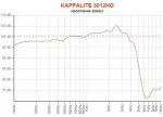
What am I really looking for here? From what I know of SMAART and it's displays, it seems that that the lower end of this box is more in phase than the higher end? Especially around 2k. Is this indicative of a lows box in the PA?

I'll eventually unpack part 1. As for your other two assertions: the first makes no physical sense, and the second is incorrect.

As far as the orders go, and what 1st order, 2nd order and all that is, I am embarrassed to say that I don't know what that is, so I can't take a stab at what those are. What does one look for to see the difference between a passive and active crossover?

http://www.linkwitzlab.com/crossovers.htm

I know that's brief, but I've got a full day.
 
Re: Virtual SMAART training: Tell the crossover frequency and type

I am not really sure if the logic is reversible:

i.e. if A (an electronic crossover) creates B (an acoustic crossover), then by looking at B (an acoustic crossover) you should be able to determine A (an electronic crossover)

Indeed, as you were questioning, that logic does not always hold true. Though much can be gleaned, depending on the driver's unprocessed response, the electronic crossover can in some cases look significantly different than the final acoustic crossover. One obvious example is the case of many Eminence woofers which have a rising response that often occurs around the crossover point (see attached example where there is a peak of approx 5dB above nominal level centered at about 2.5K, and of about 8db between the low mids and this peak). Such examples can show a clear disparity between electrical and acoustic response.
 

Attachments

  • 3012HO.JPG
    3012HO.JPG
    28 KB · Views: 0
Re: Virtual SMAART training: Tell the crossover frequency and type

I'm sorry Phil, I wasn't being completely flippant. I seem to sense agreement that there is something wrong with the crossover in this box and that leads me to think that we should be guessing what the problem is rather than trying to match this up with a textbook example of filters done correctly. But I'm still not clear on what you are looking for so perhaps that's where I'm going wrong. Initially I thought (as I think a few other posters did as well) that you were asking us to identify the parameters of the electrical crossover filters used in this speaker design. But your previous post seems to say that we are looking to match up the combined loudspeaker driver PLUS electrical filter to a textbook filter description. I'm failing to see the purpose or feasibility of this at the moment since the combined response slopes will likely not be consistent over the stop bands (among other things). It's like we're sitting on a hill looking at the same cloud and commenting on what kind of animals or cars we see. Maybe I should just shut up and wait for you to lift the cloth off the birdcage.

Also, could you define "mid-range" as it applies to this powered speaker? What price range is mid-range?

Lastly, I do appreciate this kind of thing for discussion. I hope I haven't come across as otherwise.

-drew
 
Re: Virtual SMAART training: Tell the crossover frequency and type

Great thread Phil. Discussing thought process instead of answers is an excellent way to learn. Especially for folks like myself who are constantly striving to improve their knowledge base. So thanks for starting the discussion.

Before I divulge my thought process let me state that although I wrote Smaart v7, I am still a neophyte sound man and am constantly working to change this. So be gentle if I'm way off.

Looks to me to be a 4th order at 2kHz. I say this because there is roughly 180° difference at 2kHz, 45° per order. As far as topology is concerned, I'm guessing Butterworth as there is a 3dB difference at 2kHz.
 
Re: Virtual SMAART training: Tell the crossover frequency and type

But I'm still not clear on what you are looking for so perhaps that's where I'm going wrong. Initially I thought (as I think a few other posters did as well) that you were asking us to identify the parameters of the electrical crossover filters used in this speaker design. But your previous post seems to say that we are looking to match up the combined loudspeaker driver PLUS electrical filter to a textbook filter description.

I have no way of knowing the true filter topology of the electrical filters, nor do I particularly care. The resultant electrical+acoustic response is close enough to several realistic, textbook possibilities to post here at let people try to figure out what that likely textbook target topology could be.

When designing loudspeakers, only the total electro-acoustic target response matters. How the manufacturer gets to that target on the electrical side is beyond my knowledge, the scope of the thread, and what matters for the sake of the loudspeaker's in room performance.

Your comments feel like tilting at windmills.
 
Re: Virtual SMAART training: Tell the crossover frequency and type

You beat me to it, Adam....

I was doing more reading to help answer some of the questions posed by others and came to the same conclusion: Butterworth, at least 4th order, and most likely 2kHz.

The resulting acoustic crossover seems steeper than a 4th order filter, though, and I suspect there are a couple of out-of-band filters on either side of the electrical crossover point... but I've been wrong before.
 
Re: Virtual SMAART training: Tell the crossover frequency and type

Great thread Phil. Discussing thought process instead of answers is an excellent way to learn. Especially for folks like myself who are constantly striving to improve their knowledge base. So thanks for starting the discussion.

Before I divulge my thought process let me state that although I wrote Smaart v7, I am still a neophyte sound man and am constantly working to change this. So be gentle if I'm way off.

Looks to me to be a 4th order at 2kHz. I say this because there is roughly 180° difference at 2kHz, 45° per order. As far as topology is concerned, I'm guessing Butterworth as there is a 3dB difference at 2kHz.

Adam,

Thanks for chiming in. Your answer is one one of the approximately four that I feel are possible candidates as being "correct." It's not my personal guess, but it is certainly one of reasonable ones.

Also, do you have any insight into the long reference delay times I am seeing with internal loopback of the generator in SMAART 7.3?
 
Re: Virtual SMAART training: Tell the crossover frequency and type

Also, do you have any insight into the long reference delay times I am seeing with internal loopback of the generator in SMAART 7.3?

Phil,

Not wanting to hijack the thread, I'll be brief. If you, or anyone, would like a more in depth response please feel free to contact me offline.

In a nutshell there is artificial delay when referencing to the signal generator. How much so will vary by device. This is because when I serve the output data to a device, I take that same data and use it as input for the virtual Generator device. Which means there is no appreciable delay. Whereas the actual output signal, at a minimum, needs to go through both a D/A and then an A/D, which does take a measurable amount of time.
 
Re: Virtual SMAART training: Tell the crossover frequency and type

Are you all reading the change in phase as going from +90 to -90 directly at 2000hz, or would you include the continuing change (like I did) after that until the phase response is solely the response from the hf?

For the 180 degree phase shift based solely on the 2000 hz, I would probably up my guess to 4th order also. It looks to me like the slope of the filter is fairly steep.

I am still thinking Bessel due to the lowered response at the crossover.

edit- it appears from the phase trace that by 4000hz (1 octave from the crossover) that the LF is no longer contributing anything to the measurement and the trace is solely based on the HF, so I guess my question is how many db down would the LF have to be (6, 12, 18, 24) not to contribute to the response?
 
Last edited:
Re: Virtual SMAART training: Tell the crossover frequency and type

...

I am still thinking Bessel due to the lowered response at the crossover.

Linkwitz-Riley and Bessel are both -6dB at the knee, while Butterworth is only -3dB at the knee. Linkwitz-Riley is essentially double-stacked Butterworth filters, while Bessel has an altogether different shape.

I've been trying to avoid posting in this thread because I don't think I know enough to have anything worth saying, so if I'm completely wrong here, please let me know.
 
Re: Virtual SMAART training: Tell the crossover frequency and type

Linkwitz-Riley and Bessel are both -6dB at the knee, while Butterworth is only -3dB at the knee. Linkwitz-Riley is essentially double-stacked Butterworth filters, while Bessel has an altogether different shape.

Actually, fourth order Bessel can look a lot like 4th order Linkwitz-Riley. CAN being the operative word, the math that defines Bessel doesn't give two shits about the frequency domain, so the point at which Bessel is defined is a matter of defensible compromise. Some DSP manufacturers say -3, some -6, and some allow the point to shift depending on filter order.
 
Re: Virtual SMAART training: Tell the crossover frequency and type

Actually, fourth order Bessel can look a lot like 4th order Linkwitz-Riley. CAN being the operative word, the math that defines Bessel doesn't give two shits about the frequency domain, so the point at which Bessel is defined is a matter of defensible compromise. Some DSP manufacturers say -3, some -6, and some allow the point to shift depending on filter order.

Oh, it's one of those deals. Thanks for the info!
 
Re: Virtual SMAART training: Tell the crossover frequency and type

Well, the HF driver is very pink and the midrange also and then there is this very steep phase role of around 2k,
which indicates that the passbands are not in phase at crossover
my bet is the microphone was quite a bit off axis
on the other side Phillip mentioned averaged traces, interesting

as for the slopes
I cheated and did some reverse engineering, so I won`t comment on that

Uwe
 
Re: Virtual SMAART training: Tell the crossover frequency and type

Adam,

Thanks for chiming in. Your answer is one one of the approximately four that I feel are possible candidates as being "correct." It's not my personal guess, but it is certainly one of reasonable ones.

If this is indeed the filter used (4th order BW at 2 kHz) how do you correct something like this? Delay the LF driver so there is less phase disparity at the crossover?
 
Re: Virtual SMAART training: Tell the crossover frequency and type

Well, the HF driver is very pink and the midrange also and then there is this very steep phase role of around 2k,
which indicates that the passbands are not in phase at crossover
my bet is the microphone was quite a bit off axis
on the other side Phillip mentioned averaged traces, interesting

as for the slopes
I cheated and did some reverse engineering, so I won`t comment on that

Uwe
the phase only rolls on the R traces. the L traces go a bit then come back. I've been puzzling over this, but given your take on it, maybe the mic is in front of the left speaker, putting it off-axis only to the right speaker?

Jason
 
Re: Virtual SMAART training: Tell the crossover frequency and type

The bluish trace is pretty flat in phase between 400 and 1000hz and again from 4000 and up. This tells me that these 2 regions are basically "in time". If there was a time offset between them then we would see a flat phase in one region with one delay setting of the analyzer but we would need to adjust the delay to see the other region as a flat line. There is indeed about 90 degrees difference in phase, which might tell us something else, but I think those 2 ranges to be pretty close in "time". If the box was designed for time coherency directly on axis then we are probably looking at a mostly on-axis measurement. Or maybe Phil just found the angle where the timing worked out but the crossover suffered. The brown/green trace has an anomaly around 600 which might be disregardable as an artifact of the measurement environment (indoor or outdoor?) but the overall magnitude and phase is quite comparable to the other side.

I'm not very familiar with Smaart. The phase traces look a bit too "singular" to me. If one is a Smaart guru, do you tend to get a feel for when the very clear looking phase trace is accurate and when it isn't? Or, is the trace always accurate?

-drew
 
Re: Virtual SMAART training: Tell the crossover frequency and type

I'm not very familiar with Smaart. The phase traces look a bit too "singular" to me. If one is a Smaart guru, do you tend to get a feel for when the very clear looking phase trace is accurate and when it isn't? Or, is the trace always accurate?

By singular I take it to mean the apparent lack of resolution and overall smoothness of the trace. This is because both traces are smoothed. The phase trace is smoothed to 12th octave and the magnitude trace is smoothed to 48th octave. Smoothing is purely a display function and can be helpful when looking at overall trends.
 
Re: Virtual SMAART training: Tell the crossover frequency and type

Ah, different smoothing for the magnitude vs phase. And, it's plainly labeled as such in the pic. I should have looked at that more carefully. Thanks.
 
Re: Virtual SMAART training: Tell the crossover frequency and type

If this is indeed the filter used (4th order BW at 2 kHz) how do you correct something like this? Delay the LF driver so there is less phase disparity at the crossover?

IMO yes, probably 4" at that microphone position, like Langston said

Uwe