It came up again in the other house, and ut bugs me every time it does.Has anyone seen any evidence or have practical experience that crossfiring tops somehow reduces cancellations.The only evidence I have ever seen was a gpa model which treats each box as a point source and did not account for one box blocking the output of the other box.
cross firing trap main?
- Thread starter Jay Barracato
- Start date
You are using an out of date browser. It may not display this or other websites correctly.
You should upgrade or use an alternative browser.
You should upgrade or use an alternative browser.
Tim Weaver
Senior
Re: cross firing trap main?
http://www.falstad.com/ripple/
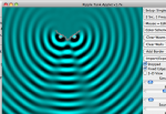
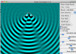
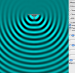
This is a Java Wave simulator. It's built for liquid waves, but it works just as well for sound, since air behaves the same way.
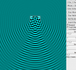
I tried to simulate 2 90 degree boxes at a right angle since this is the easiest thing to freehand. The first image is 2 cabinets in a traditional array. There's a bit of comb filtering here. This obviously changes with frequency. I just went with a default setting. The second image shows the same 2 cabinets toed in towards each other at 90 degrees. Notice there is a complete polarity flip in the middle, and the areas where the comb filtering was in the top image there is now almost complete cancellation. The middle polarity flip means you've screwed up your sub to mains integration and will have a hole in the response.
Those patrons on the sides will be plenty pissed if they paid a bunch of money to hear next to nothing.
http://www.falstad.com/ripple/
This is a Java Wave simulator. It's built for liquid waves, but it works just as well for sound, since air behaves the same way.
I tried to simulate 2 90 degree boxes at a right angle since this is the easiest thing to freehand. The first image is 2 cabinets in a traditional array. There's a bit of comb filtering here. This obviously changes with frequency. I just went with a default setting. The second image shows the same 2 cabinets toed in towards each other at 90 degrees. Notice there is a complete polarity flip in the middle, and the areas where the comb filtering was in the top image there is now almost complete cancellation. The middle polarity flip means you've screwed up your sub to mains integration and will have a hole in the response.
Those patrons on the sides will be plenty pissed if they paid a bunch of money to hear next to nothing.
Attachments
Tim Weaver
Senior
Re: cross firing trap main?
This is also true, but not something I can show well with the java applet. All you get is 360 degree radiators and walls which block the waves.
Looking at the first image there, I didn't get the boxes exactly at 90 degrees. Should be close enough though. It's hard to draw a 90 degree wall free hand with a mouse!
You're moving the acoustic origins away from each other. There is no way it makes things better.
This is also true, but not something I can show well with the java applet. All you get is 360 degree radiators and walls which block the waves.
Looking at the first image there, I didn't get the boxes exactly at 90 degrees. Should be close enough though. It's hard to draw a 90 degree wall free hand with a mouse!
Re: cross firing trap main?
Here are the GPA models for a pair of 90 degree boxes with 45 degrees each of splay.
1000 hz crossfired

1000 hz normal splay

8000 hz cross fired

8000 hz normal splay

However, it appears to me that in the crossfired position, the presence of one box does not block any of the output of the other box, as that configuration would do in real life.
Here are the GPA models for a pair of 90 degree boxes with 45 degrees each of splay.
1000 hz crossfired
1000 hz normal splay
8000 hz cross fired
8000 hz normal splay
However, it appears to me that in the crossfired position, the presence of one box does not block any of the output of the other box, as that configuration would do in real life.
Tim Weaver
Senior
Re: cross firing trap main?
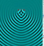
OK, I did a little more head scratching and decided that 1: I'm an idiot, and 2: the above sims represent 2 180 degree loudspeakers. I did some more practicing with the applet and found out that you can erase walls with a mouse click too, so here is my best guess at how the 2 array scenarios would apply at this one frequency.
They actually perform better than I expected, but there's a huge difference in SPL between your center area and the outsides.
Attachments
Tim Weaver
Senior
Re: cross firing trap main?
Also that center area on the crossfired array would have poor phase response because the 2 sources are further away from each other, so depending where you stand you'll be closer to one source than you are the other.
In the traditional array you don't hear the far speaker (up to a point) so it's driver doesn't get to mess with your phase. To a point anyway.
Tim Weaver
Senior

Re: cross firing trap main?
The cross fire messes up the phase response, not polarity, polarity is invariant with frequency. If you change the frequency in your wave model, the “out of phase” wave positions will change.
The cross fire idea works so poorly because it puts the maximum output of both cabinets in the area of greatest overlap, intensifying the phase cancellation resulting from different path lengths to the listening position.
Reflections off the adjacent cabinet face make for more cancellations, none of which can be EQed since they all change with angle of incidence and frequency.
At the low crossover point, say 100 Hz, splaying a pair of small front loaded speaker in or out will make little difference, as either will result in a spacing difference of less than 1/4 wavelength.
Cross firing of larger cabinets can actually be beneficial in the 100 Hz crossover region as it can reduce the center to center distance between cones to within 1/4 wavelength.
A “normal” out firing splay, with the HF horn 6 dB down point in the area of overlap will have far less comb filtering, and less deep nulls in the critical speech frequency range.
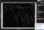
The screen shots below shows the on axis response of a single cabinet (10T EQ on). The off axis response for this cabinet is pretty uniform up to 8K out to about 40 degrees off.
The lower two traces show a pair of the same cabinets cross fired with the mic in the center of the cross fire region (10T V on), and 10 degrees off (10T V 10 off).
There is more than 20 dB variation in level, (the single cabinet was +/- 3 dB) and the null spacing changes with angle.
There is little change in the low frequency response, but above 400 Hz things go very badly, outdoors it was easy to hear how grossly the sound differed as I walked from left to right.
Unfortunately, I discarded the further off axis traces, but suffice it to say they looked even worse, and quite different at each 10 degree interval.
Indoors, the reflections from boundaries make things more complicated. If a single cabinet dispersion is wide enough, splaying a pair outward will result in wall reflections, in that case it is better to vertically stack the cabinets, usually with the HF together.
Art
Tim,http://www.falstad.com/ripple/
This is a Java Wave simulator. It's built for liquid waves, but it works just as well for sound, since air behaves the same way.
I tried to simulate 2 90 degree boxes at a right angle since this is the easiest thing to freehand. The first image is 2 cabinets in a traditional array. There's a bit of comb filtering here. This obviously changes with frequency. I just went with a default setting. The second image shows the same 2 cabinets toed in towards each other at 90 degrees. Notice there is a complete polarity flip in the middle, and the areas where the comb filtering was in the top image there is now almost complete cancellation. The middle polarity flip means you've screwed up your sub to mains integration and will have a hole in the response.
Those patrons on the sides will be plenty pissed if they paid a bunch of money to hear next to nothing.
The cross fire messes up the phase response, not polarity, polarity is invariant with frequency. If you change the frequency in your wave model, the “out of phase” wave positions will change.
The cross fire idea works so poorly because it puts the maximum output of both cabinets in the area of greatest overlap, intensifying the phase cancellation resulting from different path lengths to the listening position.
Reflections off the adjacent cabinet face make for more cancellations, none of which can be EQed since they all change with angle of incidence and frequency.
At the low crossover point, say 100 Hz, splaying a pair of small front loaded speaker in or out will make little difference, as either will result in a spacing difference of less than 1/4 wavelength.
Cross firing of larger cabinets can actually be beneficial in the 100 Hz crossover region as it can reduce the center to center distance between cones to within 1/4 wavelength.
A “normal” out firing splay, with the HF horn 6 dB down point in the area of overlap will have far less comb filtering, and less deep nulls in the critical speech frequency range.
The screen shots below shows the on axis response of a single cabinet (10T EQ on). The off axis response for this cabinet is pretty uniform up to 8K out to about 40 degrees off.
The lower two traces show a pair of the same cabinets cross fired with the mic in the center of the cross fire region (10T V on), and 10 degrees off (10T V 10 off).
There is more than 20 dB variation in level, (the single cabinet was +/- 3 dB) and the null spacing changes with angle.
There is little change in the low frequency response, but above 400 Hz things go very badly, outdoors it was easy to hear how grossly the sound differed as I walked from left to right.
Unfortunately, I discarded the further off axis traces, but suffice it to say they looked even worse, and quite different at each 10 degree interval.
Indoors, the reflections from boundaries make things more complicated. If a single cabinet dispersion is wide enough, splaying a pair outward will result in wall reflections, in that case it is better to vertically stack the cabinets, usually with the HF together.
Art
Attachments
Re: cross firing trap main?
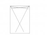
I have tried something along the same lines on a couple of occasions with fair success. The boxes were not next to each other but on either side of the stage in a 450 seat theater with very good acoustics and a lot of diffusive surfaces. One advantage is if you point them correctly the people in the front rows directly in front of the speakers don't get blasted directly. Up the middle aisle was a little weird phase wise but I couldn't really hear any cancellations. Very unscientific -I know. Crude illustration:
I have tried something along the same lines on a couple of occasions with fair success. The boxes were not next to each other but on either side of the stage in a 450 seat theater with very good acoustics and a lot of diffusive surfaces. One advantage is if you point them correctly the people in the front rows directly in front of the speakers don't get blasted directly. Up the middle aisle was a little weird phase wise but I couldn't really hear any cancellations. Very unscientific -I know. Crude illustration: