B&C Sub designs

Re: B&C Sub designs

Alan,

I think your math converting sq cm into sq inches must be off. When I converted 339 sq cm into inches I came up with a port that would be 7.255 inches x 7.255 inches = 52.6 square inches. 1sq cm = 0.155 sq in. 339.6 * 0.155 = 52. Make it whatever shape you want just keep the area at 52.6 and the Fb at 32. Your program should give you a port length pretty close to 12.5 inches. If you just model the B&C design as a 200 liter box with Fb of 32 with 52.6 sq in port area you will I'm sure come up with the F3 of 32.2 that B&C shows on their page.

And I'll bet that when you look at the B&C recommended enclosure excursion predictions in your software you will find it might exceed excursion limits in the 45 to 55 range if driven with max power. That is what I was trying to say in my previous posts. So getting the extra LF extension will cost you some power handling 1/2 octave above Fb because you will run out of excursion. But remember this driver has Xmax of 12mm and Xvar of 14mm. Xvar is apparently a more accurate parameter than traditional Xmax for reflecting how much excursion a driver can really provide prior to excessive distortion. So the usable excursion is really 14mm. Further, the driver has 28.5mm one way excursion before damage so even if linear excursion capability is exceeded at some frequencies at very high power you are unlikely to ever hurt the driver with overexcursion as long as you don't use any stupid EQ boosts and do use an appropriate hpf.

With that said, I understand that you purposely came up with a design that wouldn't exceed Xmax in the passband. That is a reasonable trade off, but I think that a design for this driver with lower Fb and F3 would handle all the power you want in the real world (up to thermal limits) and not hurt the driver but still give you extra LF extension. It's all about trade offs.

Does that make sense?

Loren

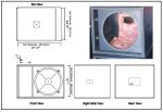
http://www.bcspeakers.com/PRD/GRP/0000000356_3.jpg

Its says a port area of 339.6 cm sq. Thats a 21 inch wide port by 6.36 tall, along with a 12.48 long port. There box is 200 liters, mine is 205 Litters.

Close enough on box volume.

I plugged the B+C port into the program, it came up with Fb 53 F3 40.4, What gives, I'm wrong or B+C has a misprint.

I got this,
3 =7.62cm
21= 53.34 cm

Using a 53.34 wide port yields 339.6 / 53.34 = 6.36 tall port on bc.
31.7 / 2.54 = 12.48 long port
 
Last edited:
Re: B&C Sub designs

I never realized this, that the eaw 528 is two seperate inclosures, same with the jbl 728, Now I know why I don't like either box. Is the yorkville ls1004 two seperate inclosures?

A double 18 can be one large enclosure or two separate enclosures. As long as the net volume per driver is the same. A 16 cf enclosure with two 18's will be the same as an 8 cf cabinet with one driver. This assumes Fb and port area per driver are the same. One reason to have the double 18 box divided into two chambers is that if you blow one driver then the single driver is effectively in a huge cabinet and exposed to the blown driver's cone flopping around as well which makes it likely the second driver will be damaged as well. I'm sure there are other reasons but that is my understanding.

Loren
 
Re: B&C Sub designs

I would also bet that you could use the 18TBW100 in a somewhat smaller enclosure with the same Fb and then add a small parametric boost right at Fb resulting in vy similar performance to the larger enclosure.
 
Re: B&C Sub designs

Alan,

I think your math converting sq cm into sq inches must be off. When I converted 339 sq cm into inches I came up with a port that would be 7.255 inches x 7.255 inches = 52.6 square inches. 1sq cm = 0.155 sq in. 339.6 * 0.155 = 52. Make it whatever shape you want just keep the area at 52.6 and the Fb at 32. Your program should give you a port length pretty close to 12.5 inches. If you just model the B&C design as a 200 liter box with Fb of 32 with 52.6 sq in port area you will I'm sure come up with the F3 of 32.2 that B&C shows on their page.

And I'll bet that when you look at the B&C recommended enclosure excursion predictions in your software you will find it might exceed excursion limits in the 45 to 55 range if driven with max power. That is what I was trying to say in my previous posts. So getting the extra LF extension will cost you some power handling 1/2 octave above Fb because you will run out of excursion. But remember this driver has Xmax of 12mm and Xvar of 14mm. Xvar is apparently a more accurate parameter than traditional Xmax for reflecting how much excursion a driver can really provide prior to excessive distortion. So the usable excursion is really 14mm. Further, the driver has 28.5mm one way excursion before damage so even if linear excursion capability is exceeded at some frequencies at very high power you are unlikely to ever hurt the driver with overexcursion as long as you don't use any stupid EQ boosts and do use an appropriate hpf.

With that said, I understand that you purposely came up with a design that wouldn't exceed Xmax in the passband. That is a reasonable trade off, but I think that a design for this driver with lower Fb and F3 would handle all the power you want in the real world (up to thermal limits) and not hurt the driver but still give you extra LF extension. It's all about trade offs.

Does that make sense?

Loren

Got it, did what you said, the b+c design will be over excursion of 12mm from 43.8 to 62.1 going by x max, going by x var its ok. I always go by x max, as thats what the program asks for.
 
Re: B&C Sub designs

Ohh, I was thinking that I was being directed to an actual cad design, not just the specs for one. I got excited for a second. Back to the drawing board! (Or Alan's drawing board )

Kip,

Everything you need is there. Box volume, port area, port length. You just design a box the shape you want leaving space in the baffle for your port. Your cabinet builder should be able to help with the specific construction details. It could be pretty similar to the B&C design with the CAD drawings. On the other hand it is nice to have a plan to build from.

Loren
 
Re: B&C Sub designs

How does B&C calculate the Xmax (excursion) specification, and what is Xvar?
- Evolution is a process that affects not only products, but also their technical specifications. Constant advances in research provide more and more precise methods to measure the performance of loudspeakers, and describe their features. Thiele – Small parameters have become the universal language for describing loudspeaker behaviour in the small signal domain. Nevertheless, they comment little on the working limits of loudspeakers in the large signal regime. These limits are customarily indicated by Xmax, the maximum linear excursion. This value, measured in our catalogue according to AES2-1984 standard, corresponds to a maximum of 10% total harmonic distortion (THD) with a sinusoidal signal. Recent research shows that this method can yield ambiguous results, and even different numerical values for the same loudspeaker. The main limit of this measurement is that it looks at the output signal instead of the physical features of the driver itself. On the contrary, the most up-to-date instruments for distortion analysis can measure the variations in loudspeaker parameters when they are fed with high-level signals. In this way, an excursion limit can be fixed, beyond which the parameter’s variation becomes excessive. The “Xvar” value reported in our data (generally after the traditional “Xmax” value) is measured this way. Beyond this excursion limit, the magnetic field seen by the voice coil, or the total suspension compliance, or both, drops to less than 50% of their small signal value, producing high distortion levels, strong variations from small signal behaviour and power compression. The new technique yields different results from the standard measurement based on THD.
 
Re: B&C Sub designs

Got it, did what you said, the b+c design will be over excursion of 12mm from 43.8 to 62.1 going by x max, going by x var its ok. I always go by x max, as thats what the program asks for.


Well glad to hear that the model matches B&C's recommendation after the conversion was cleared up. Well the higher Fb will certainly avoid the over excursion. Either one would probably work well for Kip, he just needs to pick which he wants.
 
Re: B&C Sub designs

Well glad to hear that the model matches B&C's recommendation after the conversion was cleared up. Well the higher Fb will certainly avoid the over excursion. Either one would probably work well for Kip, he just needs to pick which he wants.


My design is louder at 40 to about 57, So theres a trade off with B+c design, how many thing repdoduce 32 Hz, how many are at 50?
 
Re: B&C Sub designs

In the Phil's article that I was referred do earlier on this discussion it's recommended that the total gross dimensions of the box would be equal to the port area plus the driver chamber.

Are you guys doing that in your builds?

Also going by the B&C specs... in order for my port opening to be 339cm, my port would be 21" by 6.35". Does this look a little big to you guys? That opening would be roughly a quarter of the entire face of the box.
 

Attachments

  • OAP LF118 Mod.jpg
    OAP LF118 Mod.jpg
    182 KB · Views: 3
Last edited:
Re: B&C Sub designs

As far as program music goes that booty music gets played on NYE gig's so the ability to reproduce 40Hz is probably not a bad thing. My guess is that I'll end up with a 4th order 40Hz HPF on the subs anyways to act as a protectant to the drivers.
 
Re: B&C Sub designs

Kip,

You are correct that you add the 200L net enclosure volume to the volume occupied by the vent. You also must add the 11 liters occupied by the driver itself as well as some volume for any bracing.

Looking at your drawing, I am not sure why you still have 7" beside the driver. Is that just to get the proper enclosure volume? Or is that the vent?

Your vent at 2.5" x 21" is what B&C recommends, but it might still limit the design in the end. It wouldn't make any sense to build new boxes because your old ones have port compression only to have the new box exhibit similar problems. If you have the space to spare I would think about an even larger vent.

WinISD is a freeware product that allows you to model enclosures. It's not perfect but it may be worth using it to help you come up with a proper model for an even larger vent...

In the Phil's article that i was referred do earlier on this discussion it's recommended that the total dimensions of the box would be equal to the port area plus the driver chamber. Would the 205 (12,204 cu in) Liters come up short even with the original internal 21x3 x 7" depth port?

Going on that principle the driver chamber volume (with the above listed port size) would 192.77 liters.

So, I need to re-work the plan, correct?

The new port dimensions would 21" x 2.5" = 52.5 sq in and the depth would be 12.5 inches which equal 656.25 cu in or 10.75 liters.

Thus the total gross dimensions of the box would need to be 210.75 liters (12860 cu in or 7.44 cu ft)

Which would make the new internal dimensions 21" by 27.5" by 22.5" and something that looks like this... the port looks a little big, right?

View attachment 4622
 
Re: B&C Sub designs

It looks big to me but let me show you how i got that 7" opening...

339 sq cm is equal to 133.465 sq in.

One side of the opening is 21" so I did the division 133.465" / 21"= 6.35"

Giving me a port area of 21" by 6.35"

Is this right?


All the freeware in the world is for PC... :(

Your forgot what I for got to do, convert 6.36 cm back to inches, yielding a port opening of 2.5'' on the b + C design. So 2.5 x 21 on the b+c,12.48 deep.