B&C Sub designs
- Thread starter Kip Conner
- Start date
You are using an out of date browser. It may not display this or other websites correctly.
You should upgrade or use an alternative browser.
You should upgrade or use an alternative browser.
Attachments
Re: B&C Sub designs
Not too bad of a change then. I'm completely flexible on the 24dB HPF thing. That's usually a decision that I make once the box is setting in front of the M30 and I'm able to take some measurements. What I have historically done is just set the filters so it didn't interfere the acoustic properties of the cabinet. I've actually never own a sub that would re-produce 40Hz with any kind of authority. Even the original PAS drivers that came in these boxes begin a natural steep roll off at 50Hz. Not a very good design!
When you say that Green is the B&C and Blue is you- is the "you" a specific driver that you are referencing a theoretical ideal situation for those internal dimensions?
Re: B&C Sub designs
I forgot to ask. Does the modeling software include recommendations on internal R values for amount of insulation, if any?
I forgot to ask. Does the modeling software include recommendations on internal R values for amount of insulation, if any?
Re: B&C Sub designs
Good morning Alan and Kip,
I want to add a couple thoughts here. I don't have any modeling software nor am I in any way an expert, but I do understand that there are a lot of complexities that go into something as simple as a reflex loaded sub cabinet.
To suggest that the problem is that something is what B&C suggested seems a bit odd to me. I'm not saying that their recommended enclosure is the best enclosure for every application using this driver. However I think wisdom would be to consider that a company that produces some of the highest quality prosound drivers available has substantially knowledgeable people who come up with their suggested designs and further that they would not publish a suggested enclosure that would result in poor driver performance nor result in conditions likely to result in driver failure. I wouldn't just lightly assume that their design is crippled or poor. I also wouldn't assume that Alan's design is crippled or poor.
Alan, you say look at post 73 to demonstrate your concerns about the B&C design. You list
1)vent velocity is up there.
How high is "up there"? That is why I was suggesting to Kip that he consider an even larger vent area than the B&C design calls for just to help with keeping port behavior reasonable. Both of the proposed designs have compromised ports that will have problems at high output levels.
2)Power handling is down right where you want it not to be down, Xmax is over 12mm most of the time right in the sweet spot.
I assume you mean power handling is down due to exceeding Xmax from 45 to 56. While Xmax is 12mm, as discussed earlier in the thread Xvar is 14mm and is a more accurate reflection of the driver's performance envelope. Using Xvar and looking at your models in post 73, the B&C design stays under Xvar at all frequencies down to 32hz. Your design exceeds Xvar at more like 38hz. I think you were running that simulation at 3000 watts.
3)Dip in SPL right in the most important part.
The B&C design does have less output in the 45 to 55 range than your design does. This is with a cold voice coil. The design will become less damped as the voice coil heats up and there will be a ripple or increase in the output likely in that portion of the spectrum.
The question is whether you go with the design with somewhat higher Fb or one with lower Fb. To me, as long as the driver is within excursion limits (I would use Xvar here) in the 50 hz range then a lower Fb makes sense. Why leave that capability on the table if you don't have to. Then it comes to port behavior. If the port can't keep up at high output levels then either design will be compromised by that. Port modeling is way beyond my knowledge/skill level. Phil's article again provides good insight. Look at the pic of the Clair Bowtie sub. Huge port area on a sub that is universally respected as being very good.
PASSBAND, llc | Articles
I would just suggest using the largest port yu can reasonably fit in your box regardless of where you choose to put Fb.
I know thats the problem, its what b+c suggested, look at post 73. You said you plan on doing a 24 db high pass at 40 hz, to protect the speakers, problem is the big problem is from 45 to 56 ish with that port design. When I wake up I'll give you a new port opening to your new box dimensions, this opening will increase spl from 44 to 56 and not exceed x max, and will handle 1500w in that area.
Yes on the program, get it you'll love it.
US Speaker - Eminence Speaker Cabinet Design Software for designing professional speaker cabinets.
Re: B&C Sub designs
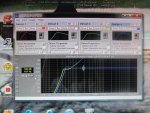
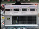
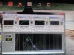
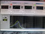
All these designs are based around the B+C tbw 100, the driver you have, Green is what would happen if you use b+c port, Me is the blue, my port
Not too bad of a change then. I'm completely flexible on the 24dB HPF thing. That's usually a decision that I make once the box is setting in front of the M30 and I'm able to take some measurements. What I have historically done is just set the filters so it didn't interfere the acoustic properties of the cabinet. I've actually never own a sub that would re-produce 40Hz with any kind of authority. Even the original PAS drivers that came in these boxes begin a natural steep roll off at 50Hz. Not a very good design!
When you say that Green is the B&C and Blue is you- is the "you" a specific driver that you are referencing a theoretical ideal situation for those internal dimensions?
All these designs are based around the B+C tbw 100, the driver you have, Green is what would happen if you use b+c port, Me is the blue, my port
Re: B&C Sub designs
Buy some 3.5 '' fiberglass insulation, staple it down with a couple hundred staples and call it good, The program doesn't give r values, it gives how much your putting in. I just use the typical, they have a none, light, and heavy insulation to pick from.
.
I forgot to ask. Does the modeling software include recommendations on internal R values for amount of insulation, if any?
Buy some 3.5 '' fiberglass insulation, staple it down with a couple hundred staples and call it good, The program doesn't give r values, it gives how much your putting in. I just use the typical, they have a none, light, and heavy insulation to pick from.
.
Re: B&C Sub designs
1 , the velocity is neer enough the limit with the B+c port
2 If he plans on putting 3 kw into this box, its his call, I know what I would do
3 Less output where you want it is less output, given hot or cold, plus again what goes down to 35 hz?
Good morning Alan and Kip,
I want to add a couple thoughts here. I don't have any modeling software nor am I in any way an expert, but I do understand that there are a lot of complexities that go into something as simple as a reflex loaded sub cabinet.
To suggest that the problem is that something is what B&C suggested seems a bit odd to me. I'm not saying that their recommended enclosure is the best enclosure for every application using this driver. However I think wisdom would be to consider that a company that produces some of the highest quality prosound drivers available has substantially knowledgeable people who come up with their suggested designs and further that they would not publish a suggested enclosure that would result in poor driver performance nor result in conditions likely to result in driver failure. I wouldn't just lightly assume that their design is crippled or poor. I also wouldn't assume that Alan's design is crippled or poor.
Alan, you say look at post 73 to demonstrate your concerns about the B&C design. You list
1)vent velocity is up there.
How high is "up there"? That is why I was suggesting to Kip that he consider an even larger vent area than the B&C design calls for just to help with keeping port behavior reasonable. Both of the proposed designs have compromised ports that will have problems at high output levels.
2)Power handling is down right where you want it not to be down, Xmax is over 12mm most of the time right in the sweet spot.
I assume you mean power handling is down due to exceeding Xmax from 45 to 56. While Xmax is 12mm, as discussed earlier in the thread Xvar is 14mm and is a more accurate reflection of the driver's performance envelope. Using Xvar and looking at your models in post 73, the B&C design stays under Xvar at all frequencies down to 32hz. Your design exceeds Xvar at more like 38hz. I think you were running that simulation at 3000 watts.
3)Dip in SPL right in the most important part.
The B&C design does have less output in the 45 to 55 range than your design does. This is with a cold voice coil. The design will become less damped as the voice coil heats up and there will be a ripple or increase in the output likely in that portion of the spectrum.
The question is whether you go with the design with somewhat higher Fb or one with lower Fb. To me, as long as the driver is within excursion limits (I would use Xvar here) in the 50 hz range then a lower Fb makes sense. Why leave that capability on the table if you don't have to. Then it comes to port behavior. If the port can't keep up at high output levels then either design will be compromised by that. Port modeling is way beyond my knowledge/skill level. Phil's article again provides good insight. Look at the pic of the Clair Bowtie sub. Huge port area on a sub that is universally respected as being very good.
PASSBAND, llc | Articles
I would just suggest using the largest port yu can reasonably fit in your box regardless of where you choose to put Fb.
1 , the velocity is neer enough the limit with the B+c port
2 If he plans on putting 3 kw into this box, its his call, I know what I would do
3 Less output where you want it is less output, given hot or cold, plus again what goes down to 35 hz?
Re: B&C Sub designs
He is saying that blue is his design for TBW100 and green is B&C design. If you aren't getting 40 hz solidly out of this driver then you indeed have a bad design.
He is saying that blue is his design for TBW100 and green is B&C design. If you aren't getting 40 hz solidly out of this driver then you indeed have a bad design.
Not too bad of a change then. I'm completely flexible on the 24dB HPF thing. That's usually a decision that I make once the box is setting in front of the M30 and I'm able to take some measurements. What I have historically done is just set the filters so it didn't interfere the acoustic properties of the cabinet. I've actually never own a sub that would re-produce 40Hz with any kind of authority. Even the original PAS drivers that came in these boxes begin a natural steep roll off at 50Hz. Not a very good design!
When you say that Green is the B&C and Blue is you- is the "you" a specific driver that you are referencing a theoretical ideal situation for those internal dimensions?
Re: B&C Sub designs
I just don't know a lot of this x max vs xvar, I don't see a lot of x var ratings, so I don't know which one to trust, well I do, x max, lol. B+C is not a poor design, just something I wouldn't do, theres more music coming from 40 -60 then 40 down, so why comprimise it in the port design
I just don't know a lot of this x max vs xvar, I don't see a lot of x var ratings, so I don't know which one to trust, well I do, x max, lol. B+C is not a poor design, just something I wouldn't do, theres more music coming from 40 -60 then 40 down, so why comprimise it in the port design
Re: B&C Sub designs
What I discussed with my carpenter is that for the prototype we are going to make the port wall remove-able so we can experiment with the depth of the shared wall the separates the the drive chamber from the port chamber. Cutting two different size walls- one that is 8" and one that is 12" and seeing the real world sonic attributes. It's not that I don't trust the software, it's a lot like FFT RTA- at some point you have to put down the computer and let your gut do some work. I'm a big proponent of modeling to get you in the ballpark. I think that it's convinced me to purchase a newer PC laptop. Another thread maybe?
Loren- I hear you loud and clear with the B&C specs and port size. I trying to find the balance between these two worlds!
Re: B&C Sub designs
I think only B&C is using Xvar and I personally trust it to be a true reflection of driver ability.
Yes their is less content in the sub 40hz range, but Kip did list "booty music" as part of his program material which will have more content down lower.
Again, sub design done well requires a lot of knowledge and experience. I don't have that. What I would do with this driver though is probably shoot for an Fb in between the B&C design (32) and Alan's design (42). I would think an Fb in the range of 35-37 would address some of the concerns Alan has about output around 50hz and still offer some extra LF extension. Once I had chosen that then I would use the largest port possible. The proposed ports both have very high velocities that will compromise output at high drive levels.
Alan, what would it look like if you modeled Fb of 37 with a port more like 5" by 21"?
BTW, I'm not trying to say Alan's design is a bad choice either.
I just don't know a lot of this x max vs xvar, I don't see a lot of x var ratings, so I don't know which one to trust, well I do, x max, lol. B+C is not a poor design, just something I wouldn't do, theres more music coming from 40 -60 then 40 down, so why comprimise it in the port design
Re: B&C Sub designs
Good plan on adjusting port length once the thing is actually built. Just sweep a sine wave until excursion is at its minimum and that is Fb
Good plan on adjusting port length once the thing is actually built. Just sweep a sine wave until excursion is at its minimum and that is Fb
What I discussed with my carpenter is that for the prototype we are going to make the port wall remove-able so we can experiment with the depth of the shared wall the separates the the drive chamber from the port chamber. Cutting two different size walls- one that is 8" and one that is 12" and seeing the real world sonic attributes. It's not that I don't trust the software, it's a lot like FFT RTA- at some point you have to put down the computer and let your gut do some work. I'm a big proponent of modeling to get you in the ballpark. I think that it's convinced me to purchase a newer PC laptop. Another thread maybe?
Loren- I hear you loud and clear with the B&C specs and port size. I trying to find the balance between these two worlds!
Re: B&C Sub designs
Your largest port possible is the only problem You could make a 5'' port by 21 '' wide but it would be over 21'' in depth. The port I listed is fine and he will here no port noise.
I think only B&C is using Xvar and I personally trust it to be a true reflection of driver ability.
Yes their is less content in the sub 40hz range, but Kip did list "booty music" as part of his program material which will have more content down lower.
Again, sub design done well requires a lot of knowledge and experience. I don't have that. What I would do with this driver though is probably shoot for an Fb in between the B&C design (32) and Alan's design (42). I would think an Fb in the range of 35-37 would address some of the concerns Alan has about output around 50hz and still offer some extra LF extension. Once I had chosen that then I would use the largest port possible. The proposed ports both have very high velocities that will compromise output at high drive levels.
Alan, what would it look like if you modeled Fb of 37 with a port more like 5" by 21"?
BTW, I'm not trying to say Alan's design is a bad choice either.
Your largest port possible is the only problem You could make a 5'' port by 21 '' wide but it would be over 21'' in depth. The port I listed is fine and he will here no port noise.
Re: B&C Sub designs
Port noise isnt the only concern, port compression is and compromised output is.
I know the port gets longer. I would just make it as large as possible and still be able to fit it in the enclosure. Some of that extra width in the box could be used instead to make a deeper cabinet to accommodate a longer port.
Re: B&C Sub designs
You should see what a double 18 in one inclosure looks like,
Inside dimensions, 48, 26.5, 19.5
Fb 38
F3 38.5
6 db louder all over with same power input.
Acoustic power
Why show acoustic power instead of sound pressure?
The acoustic power is the total power radiating from the speaker in every direction. As such, the acoustic power level includes the on-axis sound waves as well as the off-axis sound waves that radiate into the room at other angles, adding to the total perceived loudness. This is important because most speakers are fairly omnidirectional at low frequencies. So much of their sound energy will radiate off-axis. In contrast, the sound pressure level is valid at only one location, usually on-axis from the speaker, and it does not include the sound that radiates at other angles. Because of this, comparisons of maximum low-frequency loudness between different box designs are more accurate when using acoustic power.
What happens when an excursion limit is exceeded?
When a driver is pushed beyond its Xmax limit, it becomes increasingly nonlinear so its nonlinear distortion rises. If the driver is pushed hard enough it will reach its mechanical excursion limit (Xmech). When Xmech is reached, the driver may suffer physical damage like a torn spider or surround or a damaged coil former. The Cone Displacement graph shows just how far the driver's piston must move for a particular input power or voltage level.
Re: B&C Sub designs
Sounds like you just need to turn your boxes -6dB and join the party kidding, of course.
6 db louder all over with same power input.
Sounds like you just need to turn your boxes -6dB and join the party
Re: B&C Sub designs
I don't know what all this has to do with the discussion at hand. B&C's Xvar number represents the driver ability more accurately than the older Xmax stat. So why not use all 14mm when designing a model for the driver.
I also don't think you are right on getting 6db more output by just adding another driver. It is 3db for doubling the drivers and 3db for doubling drive level. Furthermore, two single 18" cabinets that were exactly half of the dimensions of your double 18" cabinets would have exactly the same output. There is no magic to putting two drivers in one cabinet twice the size. Two drivers in one cabinet require twice the volume for the same performance.
You should see what a double 18 in one inclosure looks like,
Inside dimensions, 48, 26.5, 19.5
Fb 38
F3 38.5
6 db louder all over with same power input.
Acoustic power
Why show acoustic power instead of sound pressure?
The acoustic power is the total power radiating from the speaker in every direction. As such, the acoustic power level includes the on-axis sound waves as well as the off-axis sound waves that radiate into the room at other angles, adding to the total perceived loudness. This is important because most speakers are fairly omnidirectional at low frequencies. So much of their sound energy will radiate off-axis. In contrast, the sound pressure level is valid at only one location, usually on-axis from the speaker, and it does not include the sound that radiates at other angles. Because of this, comparisons of maximum low-frequency loudness between different box designs are more accurate when using acoustic power.
What happens when an excursion limit is exceeded?
When a driver is pushed beyond its Xmax limit, it becomes increasingly nonlinear so its nonlinear distortion rises. If the driver is pushed hard enough it will reach its mechanical excursion limit (Xmech). When Xmech is reached, the driver may suffer physical damage like a torn spider or surround or a damaged coil former. The Cone Displacement graph shows just how far the driver's piston must move for a particular input power or voltage level.
Re: B&C Sub designs
Back in the 1980's, when there were very few 5 string basses, I'd agree with you, the low E on a four string bass is 40 Hz.
Now it seems most basses are 5 string with a low B, 31 Hz. Real lows are 1/3 octave lower than they used to be.
Loads of pop music has content down around 25 Hz, 35 Hz is a good compromise Fb for keeping box size reasonable but still providing most of the LF spectrum.
Art
Loren,Absolutely right. Unless he is doing a lot of dance music playback or rap shows etc he will probably not have a lot of sources with content below 40.
Back in the 1980's, when there were very few 5 string basses, I'd agree with you, the low E on a four string bass is 40 Hz.
Now it seems most basses are 5 string with a low B, 31 Hz. Real lows are 1/3 octave lower than they used to be.
Loads of pop music has content down around 25 Hz, 35 Hz is a good compromise Fb for keeping box size reasonable but still providing most of the LF spectrum.
Art
Re: B&C Sub designs
Thanks Art,
I was trying to make the point that having a little lower F3 is going to be to his advantage. While I mentioned the LF content of pre-recorded music your points regarding live sound sources is probably even more important. Thanks for the input.
Loren
Thanks Art,
I was trying to make the point that having a little lower F3 is going to be to his advantage. While I mentioned the LF content of pre-recorded music your points regarding live sound sources is probably even more important. Thanks for the input.
Loren
Loren,
Back in the 1980's, when there were very few 5 string basses, I'd agree with you, the low E on a four string bass is 40 Hz.
Now it seems most basses are 5 string with a low B, 31 Hz. Real lows are 1/3 octave lower than they used to be.
Loads of pop music has content down around 25 Hz, 35 Hz is a good compromise Fb for keeping box size reasonable but still providing most of the LF spectrum.
Art

