
After more than 40 years of building and designing various types of speaker cabinets, I finally have designed and built some prototypes of an entirely new (to my awareness) type of enclosure, the HyperboLine ™.
Using the plane wave output potential a hyperbola provides in one axis, and the attributes of a line array in the other axis, the HyperboLine has long distance HF (high frequency) SPL potential exceeding any conventional point and shoot or line array type system.
A true plane wave theoretically only drops at 3 dB per doubling of distance, compared to 6 dB per doubling of distance from ordinary speakers which emit some portion of a spherically shaped wave.
Line arrays can exhibit a 3 dB per doubling of distance measured in the near field due to destructive interference, good for even SPL coverage, but no better regarding "throw" than a point and shoot system using narrow horns.
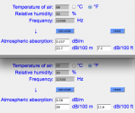
HF atmospheric air absorption attenuation is added on top of inverse distance losses.
Using this calculator:
Calculation method of absorption of sound by atmosphere air damping dissipation absorbtion - Attenuation of sound during propagation outdoors outdoor - sengpielaudio Sengpiel Berlin
We see losses at 12.5kHz range from 23.7 dB at a temperature of 68F and 50% relative humidity to 38 dB with at 77F and 20% RH .
Meyer Sound does rigorous testing, one can see that their new Leo line array is not immune to the HF air attenuation problem, as can be seen here:
http://www.meyersound.com/sites/default/files/leo_application_profile_marysville.pdf
The Leo array at 12.5 kHz drops from about 82 dB at 30 meters to 60 dB at 120m, a 22 dB drop.
Obviously 22 dB of additional HF boost is impossible, so we see the HF basically dropping in to the noise floor at 120 meters, although the rest of the audio range has only dropped about 6 dB in the same distance.
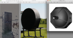
Meyer Sound introduced the SB-1 in 1997, using a parabolic dish (a paraboloid) to emit a planar (flat) wavefront. The paraboloid focuses the HF horn's reflected output parallel to the primary axis. It also uses a 12" speaker and phase processing to control the side lobes in the octave above it's 500 Hz lower limit imposed by the dish size. The SB-1 is big, 54 x 54 x 48 inches (1.38 x 1.38 x 1.23 meters) and heavy 293 lb. (133 Kg.)
Meyers spec sheet © 1997 claims a frequency response of +/- 4 dB 500-Hz -15 kHz at 100m with a maximum SPL of >110 dB at 100 meters, far greater (on paper) than the Leo's HF output potential.
Curt Graber's Hyperspike 60 set the Guinness World Record for the loudest electro-acoustic speaker at 140.2 dB at 128 meters in March of 1997.
The record has still not been broken.
Curt's HS-60 make the SB-1 seem like Marshall stack compared to a clock radio.
His commercially available HS-40 (only a bit more than one meter in diameter) can produce a warning tone of 123 dB at 100 meters, 13 dB more output than the SB-1!
The Hyperspike has the advantage over a paraboloid arrangement in that output can be scaled up by putting far more drivers in the annular ring feeding the hyperboloid. More drivers added to a paraboloid ultimately block the projector.
In 1999, after reading about the SB-1, I built a similar unit, the results were impressive, at least a 6 dB improvement in level over a conventional 13 x13 degree conical horn at long distances.
I was unaware of Curt Graber's Hyperspike record until 2009.
In recent conversations with Curt found he has been selling a fair amount of Hyperspike units worldwide, and has developed his own transducers to drive them, with assembly taking place at the 300,000 square foot Ultra Electronics plant.
Mark Gander of JBL (you old folks may remember his Cabaret Series including a 4 x10" Line Array from back in the 1980's) when touring the plant commented something like "I would rather work with you, apparently you have all the fun".
Curt is not presently selling his transducers which are to my knowledge capable of more clean mid-range output than anything on the planet.
Inspired by the Hyperspike products which use an annular ring of drivers perfect for the intended loud hailing purpose, I had the idea of using a hyperbolic waveguide using drivers in a line array, a new combination better fitted for concert sound reinforcement.
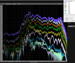
Being a combination of a line array and hyperbolic focusing waveguide, the HyperboLine does not quite achieve the 3 dB loss per doubling of distance of a true planar source, but over a 128 meter distance has around 10 dB less level loss compared to a conical 13 x 13 degree Maltese horn.
The Welter Systems Maltese horn was designed in 1992 as the HF portion of a three way co-axial horn within a horn within a horn, it is narrower ("longer throw") than any other horn in production I'm aware of, and probably has better projection than any single horn driver projector other than the Meyers SB-1. Comparative tests were between the Maltese Horn and the Hyperboline were done on Red Dog Road by my shop.
Oriented in a line, the HyperboLine can effectively paint adjacent acoustic stripes rather than spots like the SB-1 produces.
If the HyperboLine is oriented horizontally, precise digital beam steering as afforded by products like the AFGM FIRmaker could be employed, the drivers or short groups individually addressed.
Like Meyer's SB-1 testing in 1997, my recent long -distance tests have been hampered by gusty wind conditions.
Even in near worst case test conditions, blow-your-hat-off winds gusting with peaks over 30 miles per hour, relative humidity around 17 to 20, temperatures of 70- 80F at an altitude of 6200 feet, the HyperboLine shows excellent results at distances of 128 meters (416 feet).
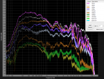
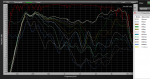
Atmospheric losses from 32 to 128 meters in the hot dry high desert test conditions should amount to around 36.5 dB at 12.5kHz in addition to the inverse distance losses compared to the predicted 22 dB air attenuation in the Meyers Leo tests conducted with 50% humidity.
A pair of HyperboLine QH-24X measure approximately a 20 dB loss at 12.5kHz between 32 to 128 meters.
Comparing the Leo and Maltese Horn results, it appears the HyperboLine shows at least a 10 dB long distance HF "throw" advantage over a line array or narrow HF horn.
The Welter Systems HyperboLine does not require the use of compression drivers, the HLQH-24X ("Quonset Hut" 24 driver experimental) uses 10 watt "full range" drivers of 83 dB sensitivity, only 93 dB continuous potential per driver.
Using high grade drivers could add some 40-45 dB potential to a unit the same size.
The charts below have been raised by 40-45 dB to "fit on the page", with decent drivers the level indicated could be achieved, with peaks +30 to 36 dB higher than the pink noise levels.
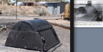
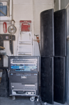
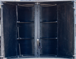
To save storage space the HLQH-24X was made with a driver section and a four part flare extender, the driver section is 33 tall x 8.25 deep x 26.25 inches wide, 29 lb., the extenders folded down are 41.5 x 16 x 3 inches, 26 lb. including attachment hardware.
Assembled the cabinet is 33" tall, 22" deep, and 41.5" wide, 55 lb.
I would like to get the chance to test the Hyperboline out in a large indoor facility to avoid wind issues, but the largest near hear is only about half the length of the tests performed.
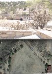
The local Madrid Oscar Huber Memorial Ballpark looked like it was 128 meters on Google maps, after setting up and measuring found that at a diagonal the longest distance was 118 meters before a steep down hill slope, with wind barreling through the arroyo.
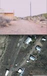
Winds were still bad, but testing turned out to be better on Red Dog Road, the HLQH-24X were set south of the sidewalk visible between the house and shop, 128 meters is by the odd shed in the north.
Science is fun, and good exercise, walked at least 5 miles during the various tests in the last few weeks, the walk is not over, though it feels longer ;^).
Art
Using the plane wave output potential a hyperbola provides in one axis, and the attributes of a line array in the other axis, the HyperboLine has long distance HF (high frequency) SPL potential exceeding any conventional point and shoot or line array type system.
A true plane wave theoretically only drops at 3 dB per doubling of distance, compared to 6 dB per doubling of distance from ordinary speakers which emit some portion of a spherically shaped wave.
Line arrays can exhibit a 3 dB per doubling of distance measured in the near field due to destructive interference, good for even SPL coverage, but no better regarding "throw" than a point and shoot system using narrow horns.
HF atmospheric air absorption attenuation is added on top of inverse distance losses.
Using this calculator:
Calculation method of absorption of sound by atmosphere air damping dissipation absorbtion - Attenuation of sound during propagation outdoors outdoor - sengpielaudio Sengpiel Berlin
We see losses at 12.5kHz range from 23.7 dB at a temperature of 68F and 50% relative humidity to 38 dB with at 77F and 20% RH .
Meyer Sound does rigorous testing, one can see that their new Leo line array is not immune to the HF air attenuation problem, as can be seen here:
http://www.meyersound.com/sites/default/files/leo_application_profile_marysville.pdf
The Leo array at 12.5 kHz drops from about 82 dB at 30 meters to 60 dB at 120m, a 22 dB drop.
Obviously 22 dB of additional HF boost is impossible, so we see the HF basically dropping in to the noise floor at 120 meters, although the rest of the audio range has only dropped about 6 dB in the same distance.
Meyer Sound introduced the SB-1 in 1997, using a parabolic dish (a paraboloid) to emit a planar (flat) wavefront. The paraboloid focuses the HF horn's reflected output parallel to the primary axis. It also uses a 12" speaker and phase processing to control the side lobes in the octave above it's 500 Hz lower limit imposed by the dish size. The SB-1 is big, 54 x 54 x 48 inches (1.38 x 1.38 x 1.23 meters) and heavy 293 lb. (133 Kg.)
Meyers spec sheet © 1997 claims a frequency response of +/- 4 dB 500-Hz -15 kHz at 100m with a maximum SPL of >110 dB at 100 meters, far greater (on paper) than the Leo's HF output potential.
Curt Graber's Hyperspike 60 set the Guinness World Record for the loudest electro-acoustic speaker at 140.2 dB at 128 meters in March of 1997.
The record has still not been broken.
Curt's HS-60 make the SB-1 seem like Marshall stack compared to a clock radio.
His commercially available HS-40 (only a bit more than one meter in diameter) can produce a warning tone of 123 dB at 100 meters, 13 dB more output than the SB-1!
The Hyperspike has the advantage over a paraboloid arrangement in that output can be scaled up by putting far more drivers in the annular ring feeding the hyperboloid. More drivers added to a paraboloid ultimately block the projector.
In 1999, after reading about the SB-1, I built a similar unit, the results were impressive, at least a 6 dB improvement in level over a conventional 13 x13 degree conical horn at long distances.
I was unaware of Curt Graber's Hyperspike record until 2009.
In recent conversations with Curt found he has been selling a fair amount of Hyperspike units worldwide, and has developed his own transducers to drive them, with assembly taking place at the 300,000 square foot Ultra Electronics plant.
Mark Gander of JBL (you old folks may remember his Cabaret Series including a 4 x10" Line Array from back in the 1980's) when touring the plant commented something like "I would rather work with you, apparently you have all the fun".
Curt is not presently selling his transducers which are to my knowledge capable of more clean mid-range output than anything on the planet.
Inspired by the Hyperspike products which use an annular ring of drivers perfect for the intended loud hailing purpose, I had the idea of using a hyperbolic waveguide using drivers in a line array, a new combination better fitted for concert sound reinforcement.
Being a combination of a line array and hyperbolic focusing waveguide, the HyperboLine does not quite achieve the 3 dB loss per doubling of distance of a true planar source, but over a 128 meter distance has around 10 dB less level loss compared to a conical 13 x 13 degree Maltese horn.
The Welter Systems Maltese horn was designed in 1992 as the HF portion of a three way co-axial horn within a horn within a horn, it is narrower ("longer throw") than any other horn in production I'm aware of, and probably has better projection than any single horn driver projector other than the Meyers SB-1. Comparative tests were between the Maltese Horn and the Hyperboline were done on Red Dog Road by my shop.
Oriented in a line, the HyperboLine can effectively paint adjacent acoustic stripes rather than spots like the SB-1 produces.
If the HyperboLine is oriented horizontally, precise digital beam steering as afforded by products like the AFGM FIRmaker could be employed, the drivers or short groups individually addressed.
Like Meyer's SB-1 testing in 1997, my recent long -distance tests have been hampered by gusty wind conditions.
Even in near worst case test conditions, blow-your-hat-off winds gusting with peaks over 30 miles per hour, relative humidity around 17 to 20, temperatures of 70- 80F at an altitude of 6200 feet, the HyperboLine shows excellent results at distances of 128 meters (416 feet).
Atmospheric losses from 32 to 128 meters in the hot dry high desert test conditions should amount to around 36.5 dB at 12.5kHz in addition to the inverse distance losses compared to the predicted 22 dB air attenuation in the Meyers Leo tests conducted with 50% humidity.
A pair of HyperboLine QH-24X measure approximately a 20 dB loss at 12.5kHz between 32 to 128 meters.
Comparing the Leo and Maltese Horn results, it appears the HyperboLine shows at least a 10 dB long distance HF "throw" advantage over a line array or narrow HF horn.
The Welter Systems HyperboLine does not require the use of compression drivers, the HLQH-24X ("Quonset Hut" 24 driver experimental) uses 10 watt "full range" drivers of 83 dB sensitivity, only 93 dB continuous potential per driver.
Using high grade drivers could add some 40-45 dB potential to a unit the same size.
The charts below have been raised by 40-45 dB to "fit on the page", with decent drivers the level indicated could be achieved, with peaks +30 to 36 dB higher than the pink noise levels.
To save storage space the HLQH-24X was made with a driver section and a four part flare extender, the driver section is 33 tall x 8.25 deep x 26.25 inches wide, 29 lb., the extenders folded down are 41.5 x 16 x 3 inches, 26 lb. including attachment hardware.
Assembled the cabinet is 33" tall, 22" deep, and 41.5" wide, 55 lb.
I would like to get the chance to test the Hyperboline out in a large indoor facility to avoid wind issues, but the largest near hear is only about half the length of the tests performed.
The local Madrid Oscar Huber Memorial Ballpark looked like it was 128 meters on Google maps, after setting up and measuring found that at a diagonal the longest distance was 118 meters before a steep down hill slope, with wind barreling through the arroyo.
Winds were still bad, but testing turned out to be better on Red Dog Road, the HLQH-24X were set south of the sidewalk visible between the house and shop, 128 meters is by the odd shed in the north.
Science is fun, and good exercise, walked at least 5 miles during the various tests in the last few weeks, the walk is not over, though it feels longer ;^).
Art
Attachments
-
 HLQH-24X.png207.6 KB · Views: 3
 -
 Hyperbolineâ„¢, HS-60,SB-1.png172.6 KB · Views: 3
 -
 HypExtPair 1to 128M.png148.6 KB · Views: 2
 -
 Maltese 1to128.png170 KB · Views: 3
 -
 Hyp&Amprack.png246.8 KB · Views: 4
 -
 Extenders Flat.png218.9 KB · Views: 3
 -
 Atmospheric absorption.png50 KB · Views: 1
 -
 North Corner Madrid Ballpark.jpg215.7 KB · Views: 3
 -
 RedDogRoad.jpg193.7 KB · Views: 3
Last edited:


 ~:-o~
~:-o~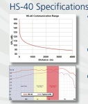
") And no, I could not wander off anywhere!! Big brother watching!!
And no, I could not wander off anywhere!! Big brother watching!!  The hyperspike products were only a small section of the factory.