I/O panel configuration

BJ James

Junior
Jan 11, 2011
260
0
0
Not really a question- rather just curious about how some of you configure your amp rack I/O patch panels. I like to use a few smaller racks that can be sent out with separate systems. So far the prefered panels I get cut are L in/R in/Sub in (XLR) - NL4 L out/NL4 R out/NL4 Sub out/NL4 Sub out (NL4)- L out/R out/ Sub out (XLR) I'll see if I can find a pic, but it's laid out like this:
I I I S S S S O O O
I have included Sub ins and out to facilitate aux fed subs when desired. The XLR ins go to a DSP in each rack-XLR outs are to feed additional racks.
Cheers,
BJ
 
Re: I/O panel configuration

My amps are set up as pairs of Itech HDs in custom 4U racks with all the connectors on the side. They have L14-30 in and through, AES digital in (which is 2 channels), 2 Ethercon jacks, and 2 NL4s wired straight off the amps. So all 4 amp channels are available on the 2 NL4s.

They are set up this way so I can easily carry them or lift them into a van myself - I got really sick of carrying around 300LB amp racks that just totally waste space. My new setup enables me to do everything those racks did and more. Since I have DSP in the amps, and there are 2 amps in a rack, having the single AES digital signal makes sense for 90% of the shows I do. Most often, one rack biamps a main and runs two channels of subs, and the other rack does the same. In the off chance that I'm running monitors or something and need more inputs, the back of the amps are accessible to patch in directly. Also, for rentals, I usually switch the AES input into an analog input and just tell the client to plug the board in there.

One rack has a router in the back and the Ethercons are for jumping the racks together so they are all on the network.

I'll see if I can dig up a picture.
 
Re: I/O panel configuration

Hi BJ,

So far the prefered panels I get cut are L in/R in/Sub in (XLR) - NL4 L out/NL4 R out/NL4 Sub out/NL4 Sub out (NL4)- L out/R out/ Sub out (XLR) I'll see if I can find a pic, but it's laid out like this:
I I I S S S S O O O

I'd keep the line-level stuff together (and cabled to the opposite side from the speaker stuff).

In my FOH rack, I have 4+4 XLRs arranged as:

patch.png


OutA and OutB are spare outputs from a processor to drive other amps for fills and stuff.

Speaker outputs are on the right on NL8s.


Nick
 
Re: I/O panel configuration

I've also downsized the racks in recent years. Most of my gigs are done with just one person, so the 250 lb., 15-space amp racks just had to go. Part of the problem was solved by going to powered subs (half the size of the previous ones), and the rest was facilitated by ditching the bi-amped monitors and mid-highs I had used since 1990, and going to higher power amplifiers running full range. I had a number of 6-space racks used for the bi-amped monitors, and those now have a pair of QSC PLX1804 amps in them, with some old TDM crossovers to highpass the racks used for mains (with the powered subs).

When I was buying the amps, the salesman tried to sell me on PLX2502s instead, but since I figured I would usually only load them at 8Ω, and only sometimes to 4Ω, I went with the lighter, cheaper, but higher voltage models. The 2502 wouldn't really have been much of a step up in power from the Carver PM1.5s I was replacing. The more shallow 1804s also allow the I/O panels to be mounted in the back of the 16" deep racks. Initially, I set them all up as 4-channel racks, with 4 pairs of male and female XLRs for the inputs, and 4 pairs of NL4s for the outputs, with pairs 1 and 3 carrying two channels from the amps. The monitors have been modified so that either channel can be picked up by the speaker, depending on which of the two input jacks you use. You can then loop to another box and have it on the same or other output of the amp.

That worked well, until I realized that I had more amp channels than speakers, and I started thinking about bridging some of the amps. QSC doesn't recommend bridging the '04 series, but running stereo with a 4Ω load is really no different than bridging into an 8Ω load, so I thought I'd give it a try. Instead of 600W available for each EV ZX3, I now have 1800W. So far, it sounds good, and nothing (speakers or amps) has blown up. The inputs of the amplifiers are fed from the HPF outputs with a Y-cable with the 2nd channel's polarity reversed.

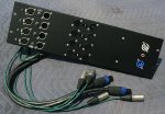
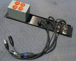
The smaller panels below are for the main racks with the bridged amps. There is only one NL4 for each output since the minimum load is 8Ω. I staggered the NL4s to make it easier to get at the latch on the lower connector, and if I ever rethink things and want to go back to bi-amping, I might add another NL4 to each channel. The orange outlets are not wired for isolated ground, I just needed back wired outlets because of the extremely tight confines of a 3" wide box on the 2 RU panel.

GTD
 

Attachments

  • RACK-1.jpg
    RACK-1.jpg
    125.5 KB · Views: 0
  • RACK-2.jpg
    RACK-2.jpg
    132.9 KB · Views: 0
  • RACK-3.jpg
    RACK-3.jpg
    152.5 KB · Views: 0
  • RACK-4.jpg
    RACK-4.jpg
    111.3 KB · Views: 0
  • RACK-5.jpg
    RACK-5.jpg
    152.5 KB · Views: 0