I got curious about the two (there may be more) methods of setting up a 2 element end-fire array and, before confusing myself with modeling programs and actual experiments, I thought I'd try to grock a simple model. Here goes. Please check my math and reasoning.
We recall that both methods involve physically spacing the sources by a distance that corresponds to an electrical delay applied to one of them, which we call "d".
In what we shall call Type A, both sources have the same polarity and the audience-side source is delayed by d.
In what we shall call Type B, the stage-side source has reverse polarity relative to the audience-side and is delayed by d.
On axis, assuming ideal omnidirectional point sources, and neglecting the level difference due to distance (equivalent to being in the extreme far field) we observe the following properties: Type A has a perfect impulse response, or, alternatively, flat magnitude and phase, on the audience side, and provides a zero (notch) at f = 1/4d on the stage-side.
Type B has perfect cancellation for all frequencies on the stage-side but has a "doubled" impulse response that corresponds to a broad hump in magnitude with the first zero at f=1/2d on the audience-side.
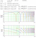
So far so good, this is all old hat to you sub-array guys. What might be interesting is the phase behavior of the two non-trivial cases, which are the stage-side of Type A and the audience-side of Type B. The graphs below (done in MathCad) show a 180 deg phase discontinuity at each zero. This is real, not a phase-wrap artifact, as the range of the Arg function, as used here, is minus pi to pi (-180 deg to +180 deg).

A few notes on the transfer function: the factor of 2 in the exponent comes from the delay being applied twice, once for the acoustic delay and once for the electric delay. The minus sign for Type B comes from the polarity flip of the stage-side source.
--Frank
We recall that both methods involve physically spacing the sources by a distance that corresponds to an electrical delay applied to one of them, which we call "d".
In what we shall call Type A, both sources have the same polarity and the audience-side source is delayed by d.
In what we shall call Type B, the stage-side source has reverse polarity relative to the audience-side and is delayed by d.
On axis, assuming ideal omnidirectional point sources, and neglecting the level difference due to distance (equivalent to being in the extreme far field) we observe the following properties: Type A has a perfect impulse response, or, alternatively, flat magnitude and phase, on the audience side, and provides a zero (notch) at f = 1/4d on the stage-side.
Type B has perfect cancellation for all frequencies on the stage-side but has a "doubled" impulse response that corresponds to a broad hump in magnitude with the first zero at f=1/2d on the audience-side.
So far so good, this is all old hat to you sub-array guys. What might be interesting is the phase behavior of the two non-trivial cases, which are the stage-side of Type A and the audience-side of Type B. The graphs below (done in MathCad) show a 180 deg phase discontinuity at each zero. This is real, not a phase-wrap artifact, as the range of the Arg function, as used here, is minus pi to pi (-180 deg to +180 deg).

A few notes on the transfer function: the factor of 2 in the exponent comes from the delay being applied twice, once for the acoustic delay and once for the electric delay. The minus sign for Type B comes from the polarity flip of the stage-side source.
--Frank
Last edited:
