QSC TouchMix 16 sound problem fixed (other touchmix versions may also get this)

Paul Lewendon

Member
Oct 8, 2019
60
11
8
54
British Columbia Canada
I fixed a problem likely heat related, as these things run a bit hot.
I hope this post helps people having a similar problem as boards are all just replacement these days, and that's pretty much the whole unit.
Note: Read the 2 addendums below from Brian.

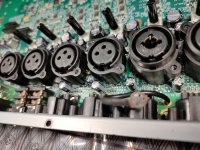
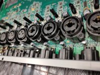
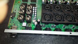
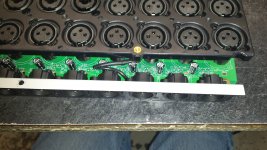
I got one of our touchmix-16 units in the other day and had to fix a low and missing some sound frequency on the right channel, I tried resetting everything just to start from scratch, but it didn't help. swapping channels(in and out) it followed it just on output. It didn't seem to appear on headphones. For some reason it was effected by the L,C,R adjustment even though I didn't expect that, but I don't have the schematics/block diagram to see how it effects it. These things do run a little hot with no fan and not much ventilation. I took the unit apart and most of the capacitors at the back of the unit along the AUX inputs and main outputs were slightly mushroomed on top (47uf/63v). Usually in electronics it's the caps in the power supply that do that, but this seemed to just be signal. 6 mushroomed of the 10 caps in the area were reading around 16uf, so I replaced all 10. It totally fixed the problem. I didn't test the Aux before taking it apart, but I'm sure they were effected as well.
I put the same temperature rating in from my stock, but probably best to find higher temp rating to help prevent it, or at least make it last longer.
I don't have the schematic to see exactly what all of the capacitors did, but I think most were just signal related.
If you're handy you could probably add a tiny fan off the supply in since those fans are such low power drain.
Normally our units aren't used every day, but I think this one was in a studio we had built(gone now) and was running
for probably a year and a half straight but only used maybe 1 or 2 days a week. For some reason some techs don't feel the need to shut thing off when not used every day.
 
Last edited:
To add a bit more to this story - we have a TM8 that was exhibiting the same problem. Low and uneven frequency response on Aux 3. I found this thread and took ours apart to find bulging blocking caps. Here's where things get interesting: I spoke to a friend of mine who does authorized service for QSC. Apparently in early production units of the TM's, the circuit boards were labelled backwards for the blocking caps, so although they appear to be installed correctly, they are backwards, meaning that if you send any of those outputs into a console with phantom power on, there's no blocking going on and the caps will fry.
So if you go to the effort of replacing the caps, check to make sure they are in correctly (positive side of the cap should make continuity with pin 2 of the output XLR - ours are backwards currently).

Hope that helps anyone else with this problem.

Cheers,
Brian
 
Yikes ! so it may not have been heat that caused it, or a combo, although since so many were bad it's hard to believe all of those channels had phantom power hooked up. Unless whatever it was hooked up to was sending out on all if phantom power is on and all those inputs are hooked up. Or it was cumulative from different shows. I double checked the drawings on the board and compared to other areas of the board with caps to make sure I didn't insert them wrong when installing, but I had no reason to doubt the drawings, especially since they were matching what came out. I'm guessing since the TM8 would have a different board than TM16 they likely wouldn't have gotten that wrong twice... I hope. It's also possible the label was just misleading, as some board labels are a bit confusing to look at making the positive appear to look like negative.
Thank you for the update/addendum.
Paul
 
Last edited:
Hey Paul,

The backwards capacitor problem affects both the TM8 and TM16 with the following main circuit board part numbers:

PC-610203-00 (TouchMix-8) or PC-610303-00 (TouchMix-16)

So if you have a main circuit board with these part numbers, you need to remove and either replace or reinstall the old capacitors but in the opposite direction of what is shown on the circuit board.

Hope that helps.

Cheers,
Brian
 
Thank you for the update, I'll open it up and take a look, I'm keeping fingers crossed that it's the newer board so I don't have to redo everything. We have a few of these units, so I wonder what the other ones are like even if it's the new boards in them.
Thanks
Paul
 
Brian;

Thanks so much for clarifying which part number of boards are affected. I pulled out my little TM-8 a couple weeks back after many months of sitting, and I was dismayed to discover that there was only a little bit of output on one of the mains. This thread really helped me get to the bottom of the problem & order some parts for repair.

I just wanted to ask a few additional questions, if you might happen to know the answers:

1) The 4 AUX outputs all have just 1x 47uF 63v electrolytic on them, but the MAIN L & R seems to have 2. Do you know the reason for this? I guess both of those caps should be reversed?? (both of them were failing on each channel)

2) Is this stencil / PCB labeling problem just isolated to the MAIN & AUX outputs? For example, is the large bank of electrolytic caps for the INPUT channels labeled correctly, should they ever fail / need to be changed?

3) Due to the worldwide shortage of electronic components, I was forced to use similar, but not identical models of capacitors, is this likely to be a problem? Eg - my board has Nichicon VZ series from the factory, but the only replacement I could find in stock (only 17 available!!) was Nichicon KW series. They are both considered "audio grade", and the same capacitance / voltage / temperature according to Mouser specs, so it's unclear to me what the difference might be.

Thanks so much for the great info in this thread

Roy
 
I hope the one unit that I fixed that made me start this thread is the only one, but I won't know til we get the others back at some point.
I took another couple of ours apart last week to see if it also had bad caps, and to compare for curiosity sake, and they didn't,
so it appears it was just that area that have the reversed capacitors.
I should have taken more pics, but you can see some of the other circuits caps there for comparison.
If the caps are the same tolerances and it's a reliable capacitor brand then you'll be fine.
Serial numbers of the actual units before taking them apart and looking at the board seem to not be a reliable way to check,
as the serial # from the one in these pictures were below the # as the bad one I fixed,
maybe the main board was replaced at some point. Unfortunately it's tricky to see by just taking off the bottom cover,
as there's stuff in the way for a clear view, but if you have good eyes and a flashlight you can see a couple at the side,
and then if you want extra clarification if they aren't noticeably "mushroomed" on top, you can do what Brian suggested,
by measuring the negative to the jack pin. The tops have score marks so they can expand upward to relieve pressure
when overheated so they don't explode like they did in the past.
 

Attachments

  • 20211109_114321.jpg
    20211109_114321.jpg
    4.6 MB · Views: 83
  • 20211109_114315.jpg
    20211109_114315.jpg
    4.7 MB · Views: 71
Last edited:
Brian;

Thanks so much for clarifying which part number of boards are affected. I pulled out my little TM-8 a couple weeks back after many months of sitting, and I was dismayed to discover that there was only a little bit of output on one of the mains. This thread really helped me get to the bottom of the problem & order some parts for repair.

I just wanted to ask a few additional questions, if you might happen to know the answers:

1) The 4 AUX outputs all have just 1x 47uF 63v electrolytic on them, but the MAIN L & R seems to have 2. Do you know the reason for this? I guess both of those caps should be reversed?? (both of them were failing on each channel)

2) Is this stencil / PCB labeling problem just isolated to the MAIN & AUX outputs? For example, is the large bank of electrolytic caps for the INPUT channels labeled correctly, should they ever fail / need to be changed?

3) Due to the worldwide shortage of electronic components, I was forced to use similar, but not identical models of capacitors, is this likely to be a problem? Eg - my board has Nichicon VZ series from the factory, but the only replacement I could find in stock (only 17 available!!) was Nichicon KW series. They are both considered "audio grade", and the same capacitance / voltage / temperature according to Mouser specs, so it's unclear to me what the difference might be.

Thanks so much for the great info in this thread

Roy
Hi Roy,

Paul summed up a good amount above, but just to clarify, the info I got indicates only the output caps were reversed, nothing else on the board. You do need to replace both of the caps on the main L/R outputs. I didn't worry about identical parts. Went to Mouser and ordered some caps with the same values and all seems fine when I was done. Also took some time to clean the encoder pot while I had mine apart as that was getting a little wonky.

Cheers,
Brian
 
I got my TM-8 back up & running again, all seems well.

When I took it apart, I didn't notice that one of the 3 connectors for the touch screen was a solid copper ribbon, I'd mistakenly thought it to be a standard multi-wire ribbon cable. When it came time to reassemble, I was utterly unable to get that copper ribbon back into it's connector. It is fragile & unwieldy. I think I might have got it in contact with the pins (or not) then I just Kapton taped it down. So far, no issues with the touch screen. I'm just guessing, but I think that data / signal ground is actually in the real multi-wire ribbon cables, and this solid copper thing is just the shield ground. I've never seen this done on any laptop, tablet or phone, so I'm hoping it's just QSC being overly cautious in their shielding of the touch panel ribbon cable.

Also, do any of you have a rather recurring problem with the 6 pin plug of the power connector, whereby you need to take a needle or jewelers screwdriver, and massage the fingers of the connectors in towards the center of the hole to make them contact solidly again? If so, have you been able to solve this permanently? I was contemplating taking a 6 pin XLR set, and mounting the male panel side in the mixer, and then re-wiring the power brick to match using the female wire side of the XLR. I'd love to hear if anyone has this problem and how or if they solved it...
 
Thank you so much for this thread! My band had a gig with our TM-16 last weekend and I was like, "WTF happened to the right channel output?". Had to run the sub and main on that side fully juiced and it still sounded wimpy.

Thanks to this very timely info, I installed 10 new caps wired in opposite to the board markings (talk about a design oopie) and it is sounding even and right now.

Oh -- and for those who attempt this, the wire connectors are a major pain. The little white plugs with the skinny black wires are super tight. I actually had two of the wires pull out and I had to re-thread them into the plug. Ugly. And the small ribbon connector is a bitch to thread through the slot. But all seems to be well now, and it saved me hundreds if not the full cost of another mixer.
 
I got my TM-8 back up & running again, all seems well.

When I took it apart, I didn't notice that one of the 3 connectors for the touch screen was a solid copper ribbon, I'd mistakenly thought it to be a standard multi-wire ribbon cable. When it came time to reassemble, I was utterly unable to get that copper ribbon back into it's connector. It is fragile & unwieldy. I think I might have got it in contact with the pins (or not) then I just Kapton taped it down. So far, no issues with the touch screen. I'm just guessing, but I think that data / signal ground is actually in the real multi-wire ribbon cables, and this solid copper thing is just the shield ground. I've never seen this done on any laptop, tablet or phone, so I'm hoping it's just QSC being overly cautious in their shielding of the touch panel ribbon cable.

Also, do any of you have a rather recurring problem with the 6 pin plug of the power connector, whereby you need to take a needle or jewelers screwdriver, and massage the fingers of the connectors in towards the center of the hole to make them contact solidly again? If so, have you been able to solve this permanently? I was contemplating taking a 6 pin XLR set, and mounting the male panel side in the mixer, and then re-wiring the power brick to match using the female wire side of the XLR. I'd love to hear if anyone has this problem and how or if they solved it...
I haven't on these yet, but I occasionally "re-work" connectors on things. Sometimes the engineers need to be given a little slap. They make a connector so fragile that it should only be plugged in once and left there, and also make it proprietary so you can't just grab another off the shelf. Sure(If memory serves me) these power supplies are big bricks, and probably making it so you have a good enough one, not just whatever's laying around, but still, I'm mainly just generally speaking for electronics.
If you're going to put another male/female in-line of the power adapter, just make sure you're 100% on the wiring, and how many are being used, as sometimes there's feedback wires, unused wires, etc. Also find a good spot to securely mount whatever is going to hold the pig-tail that you're putting the new end on, and some way to not make the original connector stay connected and not keep getting bumped in transit/storage, which can be just as bad as the original problem, making it like a crow-bar on the jack.
 
Last edited:
This thread is a goldmine! I have a TM-8 with probably the same issue on the right channel.
Before I start taking out random torx screws, I wondered if anyone had actual disassembly instructions from the service manual?
Or some tips on the best sequence?
Thanks in advance!
 
QSC are pretty cagey on their service manuals. Finding them online is difficult, I could not find anything for the TM series.

What you need to remove is basically everything, except the screws that hold the metal base "weight" onto the plastic bottom of the mixer. You can leave the metal weight attached to the plastic bottom. You also need to remove the nuts around the 1/4" jacks on the top plate, as well as those torx screws around the XLR jacks, plus all the gain knobs. Before you can remove the top deck, you need to CAREFULLY remove the 2 flexes and 1 solid copper flat wire that connect the display to the main board. Exercise EXTREME caution here, I just worked on a mixer where the guy destroyed the display panel flexes. A replacement display costs $150 plus requires special authorization if you are not a QSC authorized person (I'm not). The big flex needs to be released by moving the darker plastic "ears" at each edge of the flex connector. The narrow flex & the copper flat wire pull out - carefully!! Take a picture, do not reverse them!! Then remove the plug that connects the rotator knob PCB to the main board. You should now have the main PCB completely separate from everything else.

At this stage, you'll have to decide if you want to remove the plastic support bracket from around the XLR jacks to give yourself more room to work, or if you can deal with the cramped space with the bracket in place. Up to you.

Make absolutely sure you have a quality technician's soldering station with temp control (750-800F) and a small spade tip, as well as a powerful desoldering pump. This is a multi layer board, and if you do a half assed job of desoldering, then try to pull the caps out, you will destroy the plate through holes, and you will need to install jumper wires from the legs of the capacitors to additional points on the circuit board that the plate through holes connect to on the internal layers of the PCB. At this stage, you can basically throw the board away, if you are not a super-tech. How do I know this? Because I just salvaged exactly such a board... previously worked on by a complete idiot.

Solder in your new caps, making sure that the + pin goes to the XLR pin 2 side as determined with a multi meter.

Good luck!!
 
Thanks so much for your help, Roy.
I've worked on multi-layer boards in the past and I have to admit that I have a less than stellar success rate.
I think I'll pull all the advice from here and take it to someone with more experience as the TM-8 is a bit too valuable to be a practice project.
 
I agree with Randal, unless you have some experience with the connectors and soldering and have a decent enough soldering iron, it's probably best to let someone else fix it. It may help to send them the link to this forum to support the conversation so you don't have the tech be like "great, another one of those ,I found it on the internet, just do this, guys", basically be respectful of their profession and you'll get more co-operation.
 
Last edited:
Hi all,
in the meantime additional 2 auxes of my touchmix 16 cannot be used anymore. Obviously here I found the solution :)
I purchased the unit once to support my local dealer. So it is no more under warranty now. Would I have bought it at Thomann, I had one more year warranty and also an excellent service.
My local dealer will send it to a Service Center in Germany and I expect to wait month to get it back.

My idea is now to bring the unit now to my local amp tech who is very skilled in overall electronics. He has my complete trust!

I would like him to change all caps for the main and the aux outputs with the hope that everything is fine then again.

Is there any source to get the schematics?

Questions to you guys here who repaired the unit already? The tasks list to repair the unit is obviously to find in pts #14?, right?

In terms of time to invest to repair the unit, what effort is expected approximately?

Thanks!
George
 
Schematics... good luck with that. If you know someone who works at an authorized QSC service center, you might convince them to give them to you with a nice present of a bottle of Johnnie Walker Blue or something of similar refinement. Outside of that, not a chance. Many of their power amps and the K series speakers are online though, if you search for that, you can find them on one of those manuals collections sites - obviously not authorized releases!

Anyway, no technician worth his salt will actually need schematics to replace these capacitors. I've included pics of the Touchmix 8 auxes and mains, BEFORE the caps were changed. Notice the bulging tops on some of the capacitors. The first photo below is the mains. For some reason, they have TWO capacitors on each channel - these are the caps in the "valley" BETWEEN the rear panel XLR outputs and the input XLRs:

TM8-mains-marked.jpg

These are the aux channels (just 4 on the TM8), again, it's just the electrolytic caps in the space between the rear panel at the bottom of the photo and the input XLRs in the middle of the photo.
TM8-auxes-marked.jpg

REMEMBER !!!! REGARDLESS of what the white letters & symbols on the circuit board say, you want the POSITIVE (+) side of each capacitor connected to pin 2 (hot) of the XLR output jacks. I recently worked on a mixer with a date code of 2020, and the markings on the board were STILL WRONG!!!

In terms of repair time, it should be less than 2 hours. Depends a lot on the person I guess. Be sure to warn him to be extremely careful when he separates the main board from the top panel... the flex cables from the LCD are quite short & very delicate!!!

The more I see of this mixer, the more I think that the blown caps problem may often be caused when the Touchmix is used as a sub mixer (like for drums or multi keyboards rig), and the auxes get connected to a front to house console that has phantom 48v power turned on. Since these capacitors are mounted backwards from the factory, then will pop in such a situation. Meanwhile, I have not heard too much about caps going bad on the Touchmix16 stereo auxes (7/8 & 9/10), which are on 1/4" jacks, and are much less likely to get connected to an XLR with phantom power turned on.

If anyone wants to figure out their mixer's build date:
Touchmix date code chart.JPG
 

Attachments

  • TM8-mains.jpg
    TM8-mains.jpg
    1.9 MB · Views: 30
  • TM8-auxes.jpg
    TM8-auxes.jpg
    2 MB · Views: 26
Last edited:
Hi Roy,

thanks for your reply. In the meantime I found this video:

Here the whole process is shown. As far as I saw, the guy did not mention, that the new caps have to be put in in reverse direction.

However this post and the video will help to fix the problem!
Thanks!
George

PS: We use the Mixer once a time a week for 3 hours and on gigs. I enabled phantom power for two drum overhead mics. In the last year Aux 1 and 2 get buggy. Now also 4 and 5 ...
 
Last edited:
The more I see of this mixer, the more I think that the blown caps problem may often be caused when the Touchmix is used as a sub mixer (like for drums or multi keyboards rig), and the auxes get connected to a front to house console that has phantom 48v power turned on. Since these capacitors are mounted backwards from the factory, then will pop in such a situation. Meanwhile, I have not heard too much about caps going bad on the Touchmix16 stereo auxes (7/8 & 9/10), which are on 1/4" jacks, and are much less likely to get connected to an XLR with phantom power turned on.
Yet another reason to put isolation transformers between your gear and systems that you connect to that are outside of your control. (Yes, I know that a set of decent iso transformers is a decent fraction of the cost of a Touchmix)
 
  • Like
Reactions: Tim McCulloch