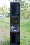
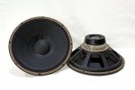
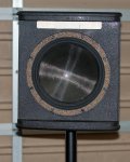
Well I have completed the 10" mid-range driver I spoke about in the previous post I made. The post was regarding three way and four way systems.
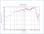
Prelim testing shows 700W AES 250-2kHz for 24Hr and 100dBSPL@1000Hz sensitivity 1W@1M adjusted for Z. Not sure what the actual power handling is yet, it could be much greater than 700W, I just chose that as a starting place and didn't do a incremental test.
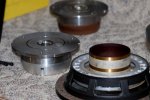
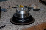
The goal was sub 1% THD+n over the operating range at 6dbV above sensitivity voltage. And that goal was achieved. Plus the better pattern control by having the diaphragm made of a high stiffness composite.
Not really sure what great use there is for a 10" mid-range, any thoughts? Personally I think an 8" mid high is the best.
EDIT.
Well after looking at the LG fp2600 docs it looks like @8Ohm nominal bridged they were 1600W max. So the two ~16Ohm drivers would have been more about 800W a piece at 0dB on the amp. during my test. I do have a I-V monitor which I will put on them later on and run a better test.
Prelim testing shows 700W AES 250-2kHz for 24Hr and 100dBSPL@1000Hz sensitivity 1W@1M adjusted for Z. Not sure what the actual power handling is yet, it could be much greater than 700W, I just chose that as a starting place and didn't do a incremental test.
The goal was sub 1% THD+n over the operating range at 6dbV above sensitivity voltage. And that goal was achieved. Plus the better pattern control by having the diaphragm made of a high stiffness composite.
Not really sure what great use there is for a 10" mid-range, any thoughts? Personally I think an 8" mid high is the best.
EDIT.
Well after looking at the LG fp2600 docs it looks like @8Ohm nominal bridged they were 1600W max. So the two ~16Ohm drivers would have been more about 800W a piece at 0dB on the amp. during my test. I do have a I-V monitor which I will put on them later on and run a better test.
Attachments
Last edited: