High Frequency Compression Driver Evaluation

Re: High Frequency Compression Driver Evaluation

Jack,

In my rough measurement of the throat angle of the 4550 and 4552 they looked identical.

Assuming the diaphragm and voice coil are the same, I would attribute the lesser LF response to the smaller compression chamber the 4552 has compared to the 4550.

Could you please check with the factory and find the exact exit angle for both drivers, and SD of each diaphragm?

Art

Hello Art,
The exit angle of the 4552 is 24 degrees.
The exit angle of the 4550 is 14 degrees.
(This makes empirical sense, as the 4552 is much shallower, and would need to open up faster to get to 1")
Also, the exit angle of the 4554 (1.4") is 26.7 degrees, and that of the 4555 (1.5") is 30 degrees.
Which also makes sense, as they need to open up faster to get to 1.4" and 1.5", instead of 1".
The 4555 and 4554 are also rated to 1khz, instead of the 800hz that the 4550 is rated to.

Getting us back to the fact that the reason that the 4552 does not go as low is that the exit opens up faster.

Regards, Jack
 
Re: High Frequency Compression Driver Evaluation

Marjan,

Thanks for the picture.
Any idea what the diaphragm total Sd (surface area) is?

Art


BMS driver with 1” VC Dome driver with 1” VC Outer Diameter/36mm 25,4mm Surface/707mm2 506mm2
BMS driver with 1,5” VC Dome driver with 1,5” VC Outer Diameter/49mm 38mm Surface/1313mm2 1134mm2
BMS driver with 1,75” VC Dome driver with 1,75” VC Outer Diameter/56mm 44,4mm Surface/1660mm2 1520mm2
 
Re: High Frequency Compression Driver Evaluation

BMS driver with 1” VC Dome driver with 1” VC Outer Diameter/36mm 25,4mm Surface/707mm2 506mm2
BMS driver with 1,5” VC Dome driver with 1,5” VC Outer Diameter/49mm 38mm Surface/1313mm2 1134mm2
BMS driver with 1,75” VC Dome driver with 1,75” VC Outer Diameter/56mm 44,4mm Surface/1660mm2 1520mm2

Jack,

I'm still not clear what the SD of the 4550/4542 diaphragms are. They have a 1.75" (44.4mm) voice coil, is the total surface area 1660mm2 or 1520mm2, or the sum of both, 3180 square mm?
 
Re: High Frequency Compression Driver Evaluation

Jack,

I'm still not clear what the SD of the 4550/4542 diaphragms are. They have a 1.75" (44.4mm) voice coil, is the total surface area 1660mm2 or 1520mm2, or the sum of both, 3180 square mm?

Hello Art, 4550/52 are 1.75" VC. They have an outer diameter of 56mm, vs 44.4 on a standard dome driver, and surface area of 1660mm2, vs, a conventional dome, which has 1520mm2.

Regards, Jack
 
Re: High Frequency Compression Driver Evaluation

Hello Art, 4550/52 are 1.75" VC. They have an outer diameter of 56mm, vs 44.4 on a standard dome driver, and surface area of 1660mm2, vs, a conventional dome, which has 1520mm2.

Regards, Jack

I see, a conventional 1.75' dome diaphragm like a JBL 2426 1" exit would be 1520mm2 Sd, the BMS 4550/4552 have 1660mm2 Sd, 8.44% larger Sd.
The Eminence PSD 2002 2" VC 1" exit dome diaphragm is about 2042mm2, about 18.7% more Sd than the BMS 4550/4552 drivers.

What is the Sd on the larger diaphragm in the BMS 4592 Coax?

Art
 
Re: High Frequency Compression Driver Evaluation

Hello Art,
The exit angle of the 4552 is 24 degrees.
The exit angle of the 4550 is 14 degrees.
(This makes empirical sense, as the 4552 is much shallower, and would need to open up faster to get to 1")
Also, the exit angle of the 4554 (1.4") is 26.7 degrees, and that of the 4555 (1.5") is 30 degrees.
Which also makes sense, as they need to open up faster to get to 1.4" and 1.5", instead of 1".
The 4555 and 4554 are also rated to 1khz, instead of the 800hz that the 4550 is rated to.

Getting us back to the fact that the reason that the 4552 does not go as low is that the exit opens up faster.

Regards, Jack

Hi Jack, Art,

Sorry if this is a dumb question. How closely related to exit angle is the shape of the wave-front? For example if the exit angle is 24 degrees, is the wave-front fairly close to a spherical arc angle of 24 degrees? Or is the wave-front flatter? Or more chaotic?

Thanks,
Michael
 
Re: High Frequency Compression Driver Evaluation

Hi Jack, Art,

Sorry if this is a dumb question. How closely related to exit angle is the shape of the wave-front? For example if the exit angle is 24 degrees, is the wave-front fairly close to a spherical arc angle of 24 degrees? Or is the wave-front flatter? Or more chaotic?

Thanks,
Michael
The exit angle will have some effect on very high frequencies which are shorter in wavelength than the exit diameter. For those VHF, the exit angle becomes a “waveguide”, as in your example if the exit angle is 24 degrees, the wave-front is fairly close to a spherical arc angle of 24 degrees.
Lower frequencies will be dependent on the horn wall angles, if the horn wall angles are wider than the driver exit angle they will be “filled” in the horn by diffraction.
 
Re: High Frequency Compression Driver Evaluation

From what B&C has told me, all of their compression drivers are designed with a flat wave front at the exit. BMS, as I understand it, are different and have an arc as has been pointed out. I am not aware of the details for drivers from any other manufacturers but I suspect that the "industry standard" for a long time was for a flat front as they were typically measured in a plane wave tube manner.

Either I am misunderstanding you, or the B&C person was wrong.
The idea is to have as phase cohesive signal at the exit of the driver. The BMS has an advantage over a traditional driver in that it has less depth to the diaphragm. That said, it does not give the BMS any advantage in the way the sound exits the driver. By definition, if the sound disperses, it has to be in an arc. You can't have a flat wave front, and dispersion, the two are mutually exclusive. If the B&C has a flat wave front, then the coverage is 1" round. No matter which driver is bolted to the horn, if it has 90degrees of coverage, the arc is going to be the same. If you take a 20' piece of string, and fix it at the mouth of the driver, and then run it around the coverage, it is going to trace out a dome, not a plane.
 
Re: High Frequency Compression Driver Evaluation

From what B&C has told me, all of their compression drivers are designed with a flat wave front at the exit. BMS, as I understand it, are different and have an arc as has been pointed out. I am not aware of the details for drivers from any other manufacturers but I suspect that the "industry standard" for a long time was for a flat front as they were typically measured in a plane wave tube manner.

I asked about this and I got this response from Roberto Magalotti, who is our head of driver research & development:

"To answer the poster's question, yes, at the driver throat the wavefront is well approximated by a spherical cap with an angle determined by the exit duct geometry, at least if the driver is well designed. Clearly, having a nice wavefront at the driver exit does not guarantee having a nice wavefront at the horn mouth, and here is where some knowledge of Acoustics and a fair amount of simulations come in handy."

Hopefully that clears up the issue. Certainly we do not design to have a flat wavefront at the driver throat, at any frequency. If you need a different wavefront shape it is best to do that with a horn, of which we offer several models. Getting this right with as little smearing as possible in the phase plug across several octaves is part of why we invest so much in R&D, and the driving force behind our latest series of drivers (e.g. DE980, DE1080, DE120) and dome technologies.
 
Re: High Frequency Compression Driver Evaluation

Some more detail that Roberto was kind enough to supply:

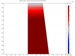
"If an image is worth a thousand words, several images are worth even more… I am attaching a small GIF I have made. It shows the wavefront shape at different frequencies from 2 to 20 kHz, at the exit of a DE980 (I have deliberately excluded the phase plug area). As you can see, the wavefront is orthogonal to the duct wall and has the shape of a circular arc, with very small variations.
When the exit angle is small, there is not a big difference between a shallow spherical cap and a flat wavefront. If the driver radiates inside a plane wave tube, the wavefront becomes flat in a short distance, at least below the cutoff frequency of the first higher order mode.
"

DE900_wavefront_shape.jpg
DE900_wavefront_shape.gif
 
Re: High Frequency Compression Driver Evaluation

Thank you Bennett for following up and clarifying this. And another thanks to Roberto for the nice animated gif. Now, does anybody have any comments about my speculation concerning the olden days and if compression drivers would likely have been measured in a plane wave manner instead of on an actual horn?

The "industry standard" for compression drivers never has been a "flat front" wave, it has always been some portion of a sphere.

All the spec sheets I have seen from the "olden days" with plane wave measurements also show the same drivers on (at least) one of their horns.
 
Re: High Frequency Compression Driver Evaluation

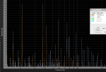
The distortion levels above do not include the (minimal) contributions of upper harmonics past the second, and are rounded to the nearest whole number above the actual 2ndHD. Anyone willing to crunch the numbers further is welcome to look at the RTA charts and derive finer resolution. Having done so in the past to prove the point that 3rd, 4th etc. harmonics, unless they exceed the second, change THD very little.
Odd order harmonics tend to sound worse (at least from a western musical standpoint) and there are differences in their levels between the drivers.
2/18/16 Revision: I noticed when comparing drivers tested recently to these tests that upper intermodulation distortion (the addition of two fundamental frequencies, 523 + 932 creating a third frequency of 1455, etc.) had been mistaken for ordinary order upper harmonics, resulting in (consistently) under reporting distortion %. Testing a 3.5" Tymphony TC9FD-18-08 "full range" driver on the Maltese horn, found that it had far less IM distortion than the best of the compression drivers, though is not capable of quite as much high frequency output due to less power handling and lower sensitivity.
 

Attachments

  • TC9, DH1A 523+932.png
    TC9, DH1A 523+932.png
    93.6 KB · Views: 7
  • TC9, DH1A 1046 & 1865.png
    TC9, DH1A 1046 & 1865.png
    88 KB · Views: 7
  • TC9, DH1a 2093+3729.png
    TC9, DH1a 2093+3729.png
    83.5 KB · Views: 7