Double 10 and Horn

Re: Double 10 and Horn

Have you considered an additional 2x 10" module that could be attached to the top of the dbl 10"+horn for higher output applications? Seems to me like it could result in an arrangement similar to your dual 12" horn (assuming the dual 10" sections would play together happily at that separation & crossover freq), and could probably be tested quite easily by stacking another cab on top, and driving only the 10"s in the top cab, and boosting the HF/VHF (c2c would be a bit more for the top cab, but if it works, customised cabs could make it work even better). Just a thought :razz:

Hi Boyd,

The double 12 actually came about because everyone loved the double 10, but they wanted more power. Often they were requesting 2 boxes a side ... which was is not the best solution.

... So I set out to build another box with 6 dB more output. With the DIY double 12 I think I ended up with more like 10dB.

Anyway … I did think of putting another two 10 inch speakers on top of the double 10 like you are suggesting, but ultimately I thought the double 12 was a better solution.

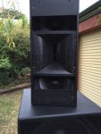
When I have a moment I should try your suggestion. FWIW I have actually flown them two deep – it seemed to work OK.
 
Peter, do you mind shareing the setting for the RCF HF950, a BMS4594 and the BMS passive crossover as a starting point for further developement?
Thanks

No problem - if I have time I will post them today. They will be for a Lake LM26 and may need some adjustment for other processors ... but it should provide a starting point.

-------------------------------------------------------------------

- BMS 4594 with crossover on RCF HF950 (not HE version)
- Crossover – Linear phase 48 dB LR simulation @ 630Hz
- If you don’t have a Lake I would use 24 dB LR @ about 675Hz

654Hz
Q 0.96
+4.1dB

1K343
Q 0.69
-3.6dB

3K22
Q 0.33
-2.7

4K6
Q 0.68
+3.3 dB

8K49
Q .82
+2.1 dB

19K06
Q 3.1
+5.3

AP 1K895 Q 3.4 2nd order
AP 12K35 Q 0.34 2nd order

On top of that there 12 more raised cosine filters - 1 to 2 dB each for minor adjustments. The most noticeable would have been a dip - 2 dB .... 5K to 8K ish.

If you have a Lake I can post these if you need.
 
Last edited:
No problem - if I have time I will post them today. They will be for a Lake LM26 and may need some adjustment for other processors ... but it should provide a starting point.

-------------------------------------------------------------------

- BMS 4594 with crossover on RCF HF950 (not HE version)
- Crossover – Linear phase 48 dB LR simulation @ 630Hz
- If you don’t have a Lake I would use 24 dB LR @ about 675Hz

654Hz
Q 0.96
+4.1dB

1K343
Q 0.69
-3.6dB

3K22
Q 0.33
-2.7

4K6
Q 0.68
+3.3 dB

8K49
Q .82
+2.1 dB

19K06
Q 3.1
+5.3

AP 1K895 Q 3.4 2nd order
AP 12K35 Q 0.34 2nd order

On top of that there 12 more raised cosine filters - 1 to 2 dB each for minor adjustments. The most noticeable would have been a dip - 2 dB .... 5K to 8K ish.
big thank you, Peter

If you have a Lake I can post these if you need.
highly appreciated - we have LM26s.

 
big thank you, Peter

highly appreciated - we have LM26s.

OK .. PEQ overlay -

I'm sure you could find a simpler solution but it seemed to work so I left it :)

1K078
Q 0.35
-1.3dB

1K451
Q 0.26
+0.7 dB

1K674
Q 0.26
+1.5dB

2K149
Q 0.23
-1.7 dB

3K163
Q 0.22
- 1.6 dB

4K1
Q 0.18
- 0.4 dB ... wouldn't bother with this or the next 2

4K711
Q 0.18
+0.5 dB

5K27
0.33
-0.4 dB

5K985 .............. 9K966
Q 0.28 ............... Q0.38
-1.9 dB ............... -1.9 dB

12K.49
Q 0.23
+2.0 dB

15K66
Q 0.24
-2.1 dB

17K65 .......... 22K24
Q 0.1 ................... Q 0.33
+1.8 dB .................. +1.8 dB
 
I've seen a few boxes where the drivers are crossed. Would there be any frequency issues? I think Yorkville does this with their Paralines. For me to save a couple of inches I would need to angle these about 30deg.

I suppose it would depend on where you cross over to the 10s. If you angle them too much, I would assume it'd start doing weird things due to HF beaming effects at higher frequencies. If you cross them lower, this should be less of an issue.

Edit: Actually, after a certain point, can't it be treated kind of like a horn?
 
I'd like to come back to the stock crossover used in this design. It seems like a rather simple crossover, although I couldn't see the component values in the photo's I've found. Of course the passive crossover will separate frequencies for us, but I'm also wondering if it's helping to flatten the response or maybe cutback on a little sensitivity?
 
I'd like to come back to the stock crossover used in this design. It seems like a rather simple crossover, although I couldn't see the component values in the photo's I've found. Of course the passive crossover will separate frequencies for us, but I'm also wondering if it's helping to flatten the response or maybe cutback on a little sensitivity?

The stock passive x-over has a x-over frequency at 6.5kHz. There is no need to cutback the sensitivity of the VHF wrt HF: they match already very good regarding sensitivity and the response is already quite flat. Note that the passive x-over has no outputs for the low-mids: it only provides outputs for the BMS driver.


Verzonden vanaf mijn iPhone met Tapatalk
 
I'd like to quickly get some opinions on an MTM configuration. I don't intend to hijack this thread. I'm just interested in this type of configuration similar to the JTR Noesis 2AX but using what Peter has put together here.

In reading about the D'Appolito configuration its suggested to space the mid/low drivers at their acoustic centers less than one wavelength apart. I'm sure this applies even in pro applications. Using this information, can someone explain how to calculate distance between each driver?
 
In reading about the D'Appolito configuration its suggested to space the mid/low drivers at their acoustic centers less than one wavelength apart. I'm sure this applies even in pro applications. Using this information, can someone explain how to calculate distance between each driver?

Wavelength = Speed of Sound divided by Frequency, so if you use a horn and compression driver that can safely play as low as 600Hz for example you could afford to have the centres of the two 10's as far apart as 573mm.

Cheers,
David.
 
Thanks David. Because Peter had set his horn to play at 650Hz I used that frequency in the wavelength calculation. If I got it right, you can see from the attached the 10's start to overlap into the RCF horn lip. The 10's are about 260mm from the horn's center. The RCF HF950's cut off frequency is 400Hz. So, I can either go down to 600Hz as you suggested, or stay at 650Hz and cut a little into the horn's outer edge so I can get the 10's closer.

dapallito-wavelength.jpg
 
I would not make cut outs in the horns: they already have dents to get the drivers as close as possible. And you need the holes to fix the horn to the cabinet and make it airtight. Since the 10"s have a lot less output than the double 12" hornloaded top, there is no issue in lowering the xover frequency a bit: the BMS has a lot of headroom with the 10"s. Also, 1" is not going to make a big difference.
 
Thanks David. Because Peter had set his horn to play at 650Hz I used that frequency in the wavelength calculation. If I got it right, you can see from the attached the 10's start to overlap into the RCF horn lip. The 10's are about 260mm from the horn's center. The RCF HF950's cut off frequency is 400Hz. So, I can either go down to 600Hz as you suggested, or stay at 650Hz and cut a little into the horn's outer edge so I can get the 10's closer.

{"data-align":"none","data-size":"custom","height":"509","title":"dapallito-wavelength.jpg","width":"525","data-attachmentid":204072}

Using the BMS 4594 with the RCF 950 you can, as noted, use a lower crossover frequency and a MTM design.

If you use an MTM design there are two issues:
  1. It becomes a little more difficult to get the HF driver up above head height.
  2. The vertical directivity of the 2 x 10” drivers operating in a dipole may not be optimal at the crossover frequency ...… don’t know ???
The picture below may be of interest - – its a prototype double 14” design with exceptional pattern control. The only issue is correcting for the peak in the response cased but the chamber in front of the 14’s.

Note - your HF horn (above sketch) should be rotated 90 degrees for this design to work.
 

Attachments

  • IMG_1589.JPG
    IMG_1589.JPG
    202.5 KB · Views: 226
OMG Peter. Nice design man. Those 14's are almost horn loaded. Maybe horn assisted. Can you explain the design a little. Why partially cover up the woofers?

A bit about the design –- unlike the double 10 & 12, this design was not focused on SPL, weight and size ...… just sound quality.

The B&C 14”" drivers are mounted in a seal enclosure. The volume in front of the drivers provides some gain around 500Hz and also acts a low pass filter to limit distortion.

The main reason to partially cover the 14’s and have two slots above and below the HF horn was to control directivity. If you don’t do that the vertical directive gets too narrow before you crossover into the horn.

This box behaves very well in every respect. The negative is that it’s a bit big and heavy and used a proprietary HF horn flare.