FIR filters

Re: FIR filters

The primary advantage of FIR filters is ability to manage the filter magnitude response in a much more finely grained manner than an IIR biquad. Causal, minimum phase FIR (i.e. no taps before reference time zero) are a very powerful tool, and far preferable than futzing around with a bunch of biquads trying to achieve the same goal.

Screwing with phase is a secondary process, and optional, with FIR.

This. Phil said it more clearly and tactfully than I could have. -F
 
Re: FIR filters

The primary advantage of FIR filters is ability to manage the filter magnitude response in a much more finely grained manner than an IIR biquad. Causal, minimum phase FIR (i.e. no taps before reference time zero) are a very powerful tool, and far preferable than futzing around with a bunch of biquads trying to achieve the same goal.

Screwing with phase is a secondary process, and optional, with FIR.

Yes, what a joy, managing magnitude with minimum phase FIR. Even the freeware rephase is capable of over 250 EQs per band.

Brand new to FIR, but I accomplished more magnitude flattening in one day with rephase, than in over half-a-year with the EQs available in mixer and DSP amp.
Haven't ventured into biquads...can't see the need...???

Also for me, phase flattening seems far from optional......
With my limited IIR crossover tuning skills, using linear phase filters makes it so damn comparatively easy to get flat magnitude through the x-over critical region...
Even I can handle aligning two flat phase traces sitting on zero :D~:-D~:grin:
 
It's taken a little more time than I expected but the FIR filter design tool is now generally available - see www.eclipseaudio.com.au. Without a license key, everything works except for filter export. I've designed the workflow to (hopefully) be practical for designers and installers, but check it out even if you just want to learn more about how FIR filters work.

Re: FIR filters
For the last 16 months I've been working on a PC/Mac application to design arbitrary FIR filters for DSP based loudspeakers and install systems with FIR DSP capability. ..... I hope to have this ready for proper release in the next few months.
Re: FIR filters
On the weekend just gone I used Michael's tool to generate some FIRs for a speaker already installed in a room. Got the response to be +/- 1.5dB from my target curve in most places in coverage of speaker barring within about 2.5m of a wall.
Just a proof of concept for me, but I was stunned at the result...


It's taken a little more time than I expected but the FIR filter design tool is now generally available - see www.eclipseaudio.com.au. Without a license key, everything works except for filter export. I've designed the workflow to (hopefully) be practical for designers and installers, but check it out even if you just want to learn more about how FIR filters work.

That looks great Michael ... fantastic ..... I just wish I could export the correction data to my Lakes :-(
 
It's taken a little more time than I expected but the FIR filter design tool is now generally available - see www.eclipseaudio.com.au. Without a license key, everything works except for filter export. I've designed the workflow to (hopefully) be practical for designers and installers, but check it out even if you just want to learn more about how FIR filters work.


Michael,
Quick question on licensing. Is the licence good for just one machine? Is it movable at all?
 
It's taken a little more time than I expected but the FIR filter design tool is now generally available - see www.eclipseaudio.com.au. Without a license key, everything works except for filter export. I've designed the workflow to (hopefully) be practical for designers and installers, but check it out even if you just want to learn more about how FIR filters work.

Great Michael, already started trying to learn the demo. Especially like the compatibility with miniDSP .
Hey, but one alert .......Win10 Defender says there is a trojan... fathale.b!plock.

edit: I see there is controversy as to whether this is a false positive type virus or not
but i still figure you would want to know what's showing up on download......sorry for any alarm


Last edited:
I scanned both the installer and the installed program files (windows) and no virus issues were reported.

That's Good !

On both my laptop and desktop Win10 machines ....Windows Defender, History tab, All detected items button, listed the trojan.
The times for the trojan's origination's exactly matched the installation times. So no question for me.that it's tied to the program..
I would not have known it was there except for notification from desktop. Laptop did not notify.
I'm guessing a false positive....???
 
Michael,
Quick question on licensing. Is the licence good for just one machine? Is it movable at all?

Hi David,
One license gives 3 activations which are good for both OsX and Windows. (e.g. you can license 1 mac and 2 PC's, or any other combinations.) I've coded it so that once activated, the licenses can't be moved. However if a computer dies and the license is lost, I can enable the occasional extra license from the server side by increasing the activation count.

 
Hi Michael, Loving the auto-mag and phase.......(been manual only in rePhase........)

After I've imported a speaker measurement, done auto mag, done auto phase, ......how do I then overlay a crossover filter (via the Mag Adj tab?
And see final summed results?

No problem building crossover, just can't put it together with corrected mag and phase...
Thx, Mark
 
Hi Mark,

Yes crossover filters can be done on the Mag Adjust tab. In the workflow, they are applied first in the design before the Phase and Auto tabs. (The example screenshots on the website show how the manual mag and phase tabs can be used to get the corrected response in range, before the automatic methods. This helps the automatic methods do their work.)

Note that whilst low pass filters are fine, FIR can't do a perfect high pass. That is, FIR filters can't, by nature, have perfect blocking at DC, due to their finite length. In some of the plots, I've provided a checkbox to view down to -100 dB so that you can see how much rejection the final filter is providing down low.

I have plans to add another tab where the user can denote any IIR filters (analog or digital) that will be used inline with the FIR filter so that the FIR design can account for the mag and phase of these IIR filters. For example, if you know you're going to use IIR HPF for a crossover, or use a capacitor inline with a HF driver.

Best,
Michael


Hi Michael, Loving the auto-mag and phase.......(been manual only in rePhase........)

After I've imported a speaker measurement, done auto mag, done auto phase, ......how do I then overlay a crossover filter (via the Mag Adj tab?
And see final summed results?

No problem building crossover, just can't put it together with corrected mag and phase...
Thx, Mark
 
Last edited:
I was looking at the miniSharc DSP board and realised that you can put multiple processing chains in series by feeding an I2S output back into an I2S input. You could e.g. use 1 chain for overall processing and next split into 1 chain per driver for driver specific processing. After some thinking I got to the following question: is there any benefit in daisy chaining 2 or more FIR filters? I think not, because: if you have a FIR filter per driver output, you can better assign the memory/taps to 1 FIR filter (per output). This way you get more correction potential (lower frequencies) at the same or less latency. Right?
 
Hi Mark,

Yes crossover filters can be done on the Mag Adjust tab. In the workflow, they are applied first in the design before the Phase and Auto tabs. (The example screenshots on the website show how the manual mag and phase tabs can be used to get the corrected response in range, before the automatic methods. This helps the automatic methods do their work.)

Note that whilst low pass filters are fine, FIR can't do a perfect high pass. That is, FIR filters can't, by nature, have perfect blocking at DC, due to their finite length. In some of the plots, I've provided a checkbox to view down to -100 dB so that you can see how much rejection the final filter is providing down low.

I have plans to add another tab where the user can denote any IIR filters (analog or digital) that will be used inline with the FIR filter so that the FIR design can account for the mag and phase of these IIR filters. For example, if you know you're going to use IIR HPF for a crossover, or use a capacitor inline with a HF driver.

Best,
Michael


Many Thx Michael,

OK, kept having trouble seeing the effect of the Mag Adjust crossover on the bandpass i was working on..Peter's DIY 60 mid section, so I loaded in a full spectrum measurement that included a sub.
This seems to work just fine. Any HP, LP, etc, all show up as expected.

But I'm still getting what looks strange on trying to just do the MID bandpass. I'm using LR12 at 100hz and 650hz in the snip below.
It looks more like a brickwall filter, than the slopes i would expect ????


Attachments

  • photo13487.jpg
    photo13487.jpg
    165.7 KB · Views: 5
I was looking at the miniSharc DSP board and realised that you can put multiple processing chains in series by feeding an I2S output back into an I2S input. You could e.g. use 1 chain for overall processing and next split into 1 chain per driver for driver specific processing. After some thinking I got to the following question: is there any benefit in daisy chaining 2 or more FIR filters? I think not, because: if you have a FIR filter per driver output, you can better assign the memory/taps to 1 FIR filter (per output). This way you get more correction potential (lower frequencies) at the same or less latency. Right?

Peter, I'm a FIR noob for sure, but I came to the same conclusion...ie daisy chaining would only make for needless extra latency (unless maybe you're just plain short of taps)


One chaining strategy I am pursuing though, is using FIR in front of IIR crossovers, a channel of FIR for each IIR channel per driver.

I'm using miniDSP and so far haven't experienced any glitches....but I'm thinking it would be a whole lot safer and wiser to use the IIR crossovers in the amps (PLDs), (along with the amps limiters, and probably physical delay too.)

So, I'm putting all phase correction for the IIR crossovers, along with phase and magnitude correction for the drivers, into the miniDSP,......... and leaving essential x-over protection in the amp.

Watch the amp fail first haha
 
Can you send me the project file through the website email or PM?

Many Thx Michael,

OK, kept having trouble seeing the effect of the Mag Adjust crossover on the bandpass i was working on..Peter's DIY 60 mid section, so I loaded in a full spectrum measurement that included a sub.
This seems to work just fine. Any HP, LP, etc, all show up as expected.

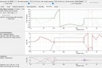
But I'm still getting what looks strange on trying to just do the MID bandpass. I'm using LR12 at 100hz and 650hz in the snip below.
It looks more like a brickwall filter, than the slopes i would expect ????
 
Hi Mark,

I loaded your project file. The reason the sides look so steep on the screenshot is that it's showing the original imported loudspeaker response - from tab 1 - after filtering with the filter you've designed. The loudspeaker response already has some low and high roll-off so this gets even steeper after applying the HP and LP filters from the mag adjust tab.

BTW, in looking over this, I found a minor bug in the updating of the target plot on tab 2. Version 1.1.2 is now available for download.

Best,
Michael


Many Thx Michael,

OK, kept having trouble seeing the effect of the Mag Adjust crossover on the bandpass i was working on..Peter's DIY 60 mid section, so I loaded in a full spectrum measurement that included a sub.
This seems to work just fine. Any HP, LP, etc, all show up as expected.

But I'm still getting what looks strange on trying to just do the MID bandpass. I'm using LR12 at 100hz and 650hz in the snip below.
It looks more like a brickwall filter, than the slopes i would expect ????
 
Last edited:
Hi Mark,

I loaded your project file. The reason the sides look so steep on the screenshot is that it's showing the original imported loudspeaker response - from tab 1 - after filtering with the filter you've designed. The loudspeaker response already has some low and high roll-off so this gets even steeper after applying the HP and LP filters from the mag adjust tab.

BTW, in looking over this, I found a minor bug in the updating of the target plot on tab 2. Version 1.1.2 is now available for download.

Best,
Michael


Many thanks Michael,

I loaded the corrections you sent me via email and tried to study what you did. I think I get a glimpse why you made the all pass addition, but am clueless re the time adjustment..I'll keep studying..don't want to waste varsity forum readers time with too many of my learning travails haha. But even with your corrections, it still looks like the passband response falls steeper than what i would expect with LR12s, on both ends ?? Does this mean I just need to flatten amplitude for the passband substantially past crossover points? In rePhase I've been trying trying to flatten to -15db points prior to overlaying x-over...I'm thinking do the same with FIR Designer...??
Very best, mark

Within reason you need to flatten the pass-band past the crossover point so that when you apply the crossover it rolls off with the exact slope and shape (of the crossover type you are using) for about the first 12dB.

The other trick you can do on the low section of the DIY is EQ it to naturally look like 12 dB Butterworth slope at 100Hz and then add a 12 Butterworth 100Hz crossover, the end result will be a 24 dB LR slope. Two 12 dB Butterworth crossovers in series = 24 dB LR.

.... also if you want to use the DIY at loud volumes I would use 24 dB crossovers.