
Re: Virtual SMAART training: Tell the crossover frequency and type
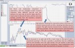
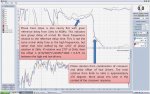
the transition zone around 2k in the phase diagramm is probably an artifact of smoothing and FPPO , multi time window or however it is called in SMAART, without these tools there should be some wild phase jumps,
so I think it doesn`t matter if it goes up or down
Uwe
the phase only rolls on the R traces. the L traces go a bit then come back. I've been puzzling over this, but given your take on it, maybe the mic is in front of the left speaker, putting it off-axis only to the right speaker?
Jason
the transition zone around 2k in the phase diagramm is probably an artifact of smoothing and FPPO , multi time window or however it is called in SMAART, without these tools there should be some wild phase jumps,
so I think it doesn`t matter if it goes up or down
Uwe


") ~
~