Re: 2" exit "line array" horn lens?
Art, I'm unfamiliar. Do share some info!
Evan
I had shared the information before on the old PSW in 2008 in a thread called "Box # 4", but I can't seem to find it anymore.
After 5 years of working with my version of a Paraline system, I am still quite pleased with it.
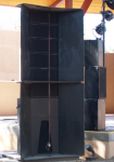
Going to the Keystone tapped horn using B&C 18SW115-4 below has also been a big improvement over the previous cabinets using Lab 12".
You have worked with the VTC system, I think mine using 8" drivers and 3" diaphragm HF eliminates a potential problem of the VTC which uses 10" and small diaphragm HF, both of which are a little out of their "comfort zone" when pushed hard in the crossover region.
Here is what I wrote in 2008:
"This fall decided to again make improvements in my high cabinets. This is now the fourth box the HF drivers (EV DH1A MT) have lived in, they have now kind of gone full circle from a concentric horn configuration, to a co-entrant configuration.
The HF drivers were purchased in 1992 to be used in a very narrow conical horn, which was nested inside of a mid horn, which was nested in a bass horn. For a variety of reasons, that design didn’t work out. The HF section alone was used for delay augmentation on a large outdoor show and I was very impressed with the sound and range of the HF drivers.
Years later used three of the drivers per side (got rid of the manifold adaptors) on narrow dispersion Maltese horns, over two dual 15” cabinets using a phase plug.
The idea was to reduce crossover points and the associated problems- “simpler is better” was the thought, listened to too many people on the Audio Asylum. After using that system for a while, it was apparent that even with the phase plug, the 15”s really did not sound good around the crossover point of 800 HZ, and the very narrow horns (about 15 degree in reality) were too narrow in most venues for only three per side.
The year was 2000, and I got to work several shows at the local shed working for QSI providing delay speakers for the lawn. Got to hear Sting with a Clair line array, then the Who with Clair S4 cabs two nights later. The difference was day and night, the line array better in every way I could think of. It was the first purpose designed line array I’d heard, but I was very impressed.
Then I got to mix on a EAW line array, and later mixed the same band on a large JBL line array. Was quite impressed with the JBLs.
I decided I had to convert my own system to a vertical array.
So box version three came about in 2001, using eight inch speakers angled in on either side of a 90x30 horn in the center. With three cabs per side, the eights were the weak link, so another box with six more eights was added per side. Various sub configurations were used over the years, but that’s another story...
Later, another side fill box was added for outer coverage, and some front fill horns. The system sounded pretty good, and was way better than the prior boxes, but had three design flaws that were bugging me:
1) The HF horns had too much vertical dispersion for a straight line array, pattern interference made them progressively non-coherent above 4K, so no amount of HF boost could correct the problem.
2) The HF horns were narrowing in horizontal dispersion above 8K.
3) The center to center cone distance of about 16 inches caused a huge (up to 20 dB) cancellation off axis in the octave around the crossover point of 1200 HZ.
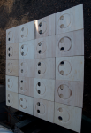
Having looked at the VTC web site, it occurred to me that the Danley/Yorkville design could solve all three problems and still allow me to use my existing box shell size.
Thanks Tom, for the explanation of what those holes do, and VTC, for the clear pictures!
I made a Paraline throat adapter for the DH1AMT, tested it out with a 90 degree conical horn, and the on and off axis response looked very similar to the VTC charts, other than the driver response variation.
One thing that blew me away during that test was removing the top and bottom of the horn made virtually no difference, so what was coming out had to be a pretty cylindrical wave front.
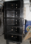
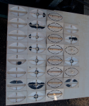
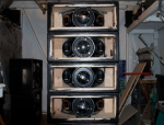
Then I tried a lot of different configurations with the cones, hoping to cram 4 into the little box. That didn’t work, and after about 100 hours of design, build and test, change build test, blah blah blah, ended up with what the pictures show.
Well, actually it took another 120 hours to finish 12 cabinets, but that included putting feet and foot alignment receptacles on 10 highs, 2 mids, and 4 subs, and removing the guts from 10 existing cabinets. The project made about a cubic yard of sawdust, but I only had to buy a couple new sheets of 1/2” plywood and one sheet of 3/4”.
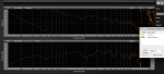
The cabinets now sound virtually identical over their 90 degree coverage pattern. With the filter set available on a DriveRack PA (not using the 1/3 octave eq), the top cabinets can be equalized +/- 3 DB on axis from 100 to about 15K, where the DH1 runs out of steam. The off axis response curves track each other almost exactly from 400 HZ up."
Since then got to use the system in a variety of indoor and outdoor shows with audiences ranging up to 10,000 people, and have been quite pleased with how even the coverage is, from standing a few feet from the stack without getting your head tore off to 300 feet out and still hearing HF details clearly.
Art

")

![paralineaddendum[1].gif](/community/data/attachments/5/5292-5c705f7b649c5ac3f8d0eb2a73e8a3f4.jpg?hash=XHBfe2ScWs)