60 Degree DIY Mid Hi - AKA PM60

Thanks David, as you suggsested & i found it.
that's a big saving on the costing chap?.
for any one else that missed it like me it's page 38 post 741
i took a look at the cad file & it is majorly different to Peter's PM 60.
It looks like the PM 90 to me less measurements.
i think it's a no go,
back to the £160 prospect i guess?.
 
Fabio if you look at the 2 drawings you will note major differences to the rear portion of the box allowing tighter arraying less weight amongst a few other things, essentially they are different boxes.
 
Thanks Carl i've emailed them.
I was also wondering how well they would marry with Ricci's Skram with B&C 21DS115-4 if i go with the B & C 12NDL76
 
Last edited:
They won't convert the drawing.
Thank you for the suggestion all the same Carl.
worsed thing is i'm running out of time and need to sort out a pair of boxes soon so it looks like i gotta go waist money on something inferier :rolleyes:
Not the espected outcome from this learning curve Oh well so much for wishfull thinking and wish the best for all who managed this brilliant project.

Hi Roger, If you are referring to this pdf
Maybe You can ask sketchup files directly to Don by PM
 
Fabio if you look at the 2 drawings you will note major differences to the rear portion of the box allowing tighter arraying less weight amongst a few other things, essentially they are different boxes.

Hi Roger,

I've been keeping track of this thread for a while and as far as i can tell Fabio is correct that the PM90 design including the dwg cad file is essentially the same as this 60 degree version. Earlier on the thread Peter mentions he cuts the corners off after finishing the build for aesthetics and a tiny weight loss and has no functional change on the sound or build process and is not essential.

Re: 60 Degree DIY Mid Hi
Just to be difficult I cut the back corners off the latest version - I makes the box look smaller and much less DIY

Re: 60 Degree DIY Mid Hi
I cut 80mm (back) x 95mm(side) off, then added a bit of 12mm ply over the corner. - it saves about 1kg.


Max who provided the drawings mentions the only change between the design is indeed the waveguide cutout to convert between the two designs.

Mark,
  • The only modification needed to make this box work with the 60 degree horn is a different cutout on the front baffle. The 4594 will still fit, though it will certainly be a tight fit! While not shown in my drawings, this design would also easily support interchangeable horns. I'd probably just add a small outside ring of bracing around the edge of the horn baffle, and use t-nuts or something better to clamp the horn down. Just some ideas.
 
Rhys I know you are just trying to help however, please go look at the cutting list for both & you will see the 60 box is made up of two parts for the side panels then the top & bottom are also different to the 90's, not something you can cut off later, but built into the box.
please stop referring to suggestions made during the development thread that I too followed rather than the factual drawings with reference to my comments as it could lead to a misinterpretation/misunderstanding of the finished product & just repeat the development thread rather than assist me in finding a means of obtaining the type of drawing that will allow me to build the box I am interested in & I have no intentions of trying to redesign this masterpiece.
yes the horns will fit both but the boxes are different.
the 60's sit tighter together when arrayed because of it. look, look, look again carefully at both rear sections, the changes at the trap section make the box just a little smaller, lighter & sexier too, things I am not willing to give up when I provide a service for a paying customer.
if they were the same box the only drawing that would have been needed for the 60's would be the front baffle.

part of what I am working on is to do with the total width of the boxes plus bass besides them sub below, so wavelength frequency and cancelation are all being taken into account when I get so fussy with my choices.
If I intended to use 1 per side then I'd just go with the 90's design but I intend 2 per side plus bass and sub.
but please don't stop making suggestions cause all the above clarification might help others in there choices.
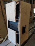
I can't speak for Max's drawing but my 60 deg and 90 boxes are the same size the difference being the cut out for the horn. I chose to cut off the back corners for the reasons Peter did, looks. That small of a cut off doesn't make a big difference for arraying them. You can't make the cut off any bigger or you will hit the 12" drivers. When I built the 60's I actually built the cut off corners into the box as my drawings showed I believe. When I built the 90s I built the boxes square and used a saw to cut off the corners then fitted a panel over the opening. Again Peter's method which was way easier than my first builds.
My boxes where cut and built by hand. My drawings were never set up for CNC like Max's. His drawings took the design to the next level.
Hope this helps.
Don
 
Any design iteration in the two threads can have the back corners angled.... just cut them off(this was not documented in any of the plans AFAIR)...... it doesn't effect horn length or path continuity ...... Essentially all iterations of the box in the two threads will come to the same great results. To my mind anybody that actually seriously wants to spend the coin and build some of these and has read the threads shouldn't need this spelt out..... it should be understood?
 

Attachments

  • back corners.jpg
    back corners.jpg
    2.9 MB · Views: 235
Don that does help me to understand how things metamorphosed, and I thank you sir all your help on both projects.
It is Max's new level I seek to attain but not easy without my tooling anymore.

I lost £70,000 in woodwork & metalwork tooling when a neighbouring fire burnt down some of the parade of workshops.
Also lost the PA system, fibreglass 2x15 bass cabs with tops coaxially mounted, community m4's, Servodrive BT7s, processing desks, amps, etc. all gone.
some of it I probably won't get back even with the insurance.
I have decided to go with a completely different design till I get things right for cnc cutting.


Any design iteration in the two threads can have the back corners angled.... just cut them off(this was not documented in any of the plans AFAIR)...... it doesn't effect horn length or path continuity ...... Essentially all iterations of the box in the two threads will come to the same great results. To my mind anybody that actually seriously wants to spend the coin and build some of these and has read the threads shouldn't need this spelt out..... it should be understood?

Really? I should read the thread where ideas developed and changed and ignore the finished drawing like you.
let me spell it out for you.
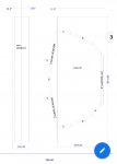
check page 3 of the pdf...Go look.. No? just want to condescend? ok I'll hand it to you on a plate then.

208929

you could cut off the top and bottom corners yes, but how does that work for cutting the two sides to create the pdf based box in the 60deg thread.
stop being so condescending and actually go look at the 2 drawings. then and only then tell me I don't understand and have more money than sense albeit in different words, and that the boxes are not different at the sides.
tell me the boxes are only different at that baffle and ignore my previous observations with Rhys.
lol--not.
 
If there is someone that would be kind enough help me attain CAD files that would be exeptable for CNC please feel free to contact me.
though it might cost me to draught them I intend to make the drawings public in the thread as mentioned to Peter.

P.S. this is what I consider as helpful input

and carl those guys you suggested are all ready to go with it when they have a CAD file, so thank you big time.
In the words of Rock and roll's unforgettable Les Clifford R.I.P. snore loudly.
 
Last edited:
  • Like
Reactions: Carl Klinkenborg
Rhys thanks for the PM, you were looking for the pdf.
try the link marked PM 60 below

PM 60

I believe you could cut off the back corners off top and bottom without issue.
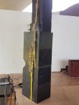
the sides are not cut off but they do change angle towards the back just cutting them off would leave gaping spaces either side of the box as you see in Jim D's picture above.
If you have tooling you could do this to the PM90 or 60's & add a piece there, 90's have a CAD drawing to go with however you could get those sides cnc cut if you have a CAD file with redone sides(If that is the right turn of phrase.
 
Last edited:
Roger, actually i was asking for a link to the forum post because i could not remember when that PDF was shared.

Anyway i found it, first page of the thread from 2015 making that version of the design over 4 years old now confirming exactly what i was thinking, that you are really entirely wrong on this and you are looking at a very old early draft.
Also worth noting the PDF you are talking about was drawn & shared by Don J Davis, who just a few posts ago is also telling you that max's version is the current one.

The version that max shared (with cad file already) is indeed several years newer and the current working version as already built by several people without issue. Won't be disagreeing with you on this any more as it seems you may have your mind made up already.
 
and carl those guys you suggested are all ready to go with it when they have a CAD file, so thank you big time.
Glad to hear it Roger; I have known them for many years but have not yet used them - let me know how you get on. They are basically a really friendly and clued-up father-and-son team whose main business is selling CNC routing machines and parts. Good luck.

Cheers, Carl.

PS. If it's any help, I travel the M5/M4/M25/A303 'triangle' so could perhaps assist in delivery to save you a penny.
 
Thanks again Carl that’s good to know.
Just got to get the angled sides plus top and bottom into the drawing.
Alternatively i go with the PM 90 CAD for CNC and have a local woodwork shop alter it to the same end but with the extra bracing.
Not ideal but possibly a beneficial compromise.
Rhys thank you for pointing out the creation time differences between the drawings as I believed the 60 thread and drawings were the latest.
I noted the differences and benefits and wish i had the skills to add the side, top & bottom differences to the CAD for CNC, even better would be if i had just missed it in the drawing but again thank you for the clarification.
A lot of thought, time & group attention went into this box so i would just like to show it & all involved the respect to get the best iteration of it i can, if possible as a flatpack without the need to alter it.
Hi Rodger,

Sorry not to notice your plight with my drawings until now! I think I could have saved you a lot of headaches here.

One thing I did not really mention in my posts about the drawings that I have mad is the story of the struggle to get to a single unified design. When I embarked on the quest to create a set of workable drawings, there were about three different versions of the drawings, all with slightly different measurement. Some had all of the parts dimension ed, others (namely Peter's) just had the critical parameters for the design.

You've been astute to notice that the final drawings resemble the 90 degree version that peter came up with after the fact. However, you seem to have missed some of the discussion that was going on with that design at the time. Peter's goal (at least as I understood it) was to create a fleet of cabinets that were largely identical with simply a difference in the horn used on the compression driver. Others (I want to say Don/Mark but I don't remember without re-reading everything) came up with the idea of having an interchangeable horn baffle, a completely trapezoidal cabinet, and several other things. As a community, we discussed the balance to be struck between thinner plywood and more bracing, how the 12" throat should be constructed, and many other things.

And so, in the summer of 2015, I set about on creating my version of the cabinet with the express idea of having it be easily mass producible. I took the large number of ideas and cut out the parts for the better part of a dozen boxes. I learned how CNC routing worked, what tolerances were necessary, and what was possible in the available materials. Anything that couldn't easily be done with a table saw and a CNC router and a single 1/4" end mill were scrapped from the design. This lead to many specific changes you will see in my cabinet, such as the lack of rear angles, a single CNC tool pass design, and baffles that were all sandwiched between two main outer pieces. I did my best to leave in flexibility for individual choices as far as handles, flyware, and connector types. I came up with a solution to the problems inherent to putting a grille on the cabinet face with the narrow cabinet width and such a wide horn. It was extremely fun, frustrating, and expensive. The process took two years and several thousand dollars of R&D/prototyping. Then the maker space that I was using for my tooling went under, and I've been unable (and unwilling) to invest in new tooling to produce them since then. Anything I build today is designed with these principles in mind, but ultimately I ensure that it's all build able by hand with a table saw and router table. Perhaps this is a bit off topic, but I wanted you to know that I identify with losing access to your tooling.

I say all this to say that the drawings that I produced were my best attempt at compiling all of the knowledge we had gained up until that point and, for all intents and purposes, the drawings I produced are the PM60 drawings. The original pdfs that you keep pointing to aren't final design plans. They are the working drawings that were used at the time, and the boxes as they exist are all different from those drawings. I sifted through all of the information available to find the critical design parameters from Peter's drawings, Don's drawings, Mark's drawings, all of the posts, and several personal emails you aren't privy to. My drawings were created using parametric CAD software to solve for the exact dimensions of the only part that isn't clearly defined - the back baffle. In this process, I took the liberty to round the baffle dimensions to their nearest whole millimeter so that the precision required for people who built the box by hand would be less daunting and not needlessly verbose. I made sure to keep the internal volumes and horn length/areas as close as possible to Peter Morris's intent, and I think avoided screwing anything up too bad acoustically or mechanically. The end result is what could easily be made into a fleet of boxes with interchangeable horns. If you want to cut off the rear corners - you can! I did my best to let you create the perfect box by modifying my drawings, or just get a "greatest hits" of the thread if you chose not to.

In conclusion, I think you've wholly misunderstood the drawings available and what they were intended to represent. I tried my best to resolve this with the drawings I posed, but clearly I left out some context in my posts regarding them and their intent. I was thinking in the context of the PM60/90 community at the time, and not the people who would stumble upon it in the future after I stopped paying a lot of attention to it. I wish you the best of luck in creating whatever version makes you happy, and I hope to see lots of pictures of your success.
 
  • Like
Reactions: Carl Klinkenborg
Oh, and Rodger - I do have a few specific technical notes to add that didn't really fit the narrative of my previous post.
  1. I did not include recommendations for the rear angles because there is no good way of cutting the angles ahead of time before assembly. The multiple compound angles required is nearly impossible with even the more advanced tooling I had access to at the time. Without the scale of many boxes, I felt it was better to simply leave out the compound angles and stick to a simple angle. Also it made the math easier!
  2. I did, however, consider the lines that would be formed by cutting those angles and made sure it was still possible without cutting into areas where handles/drivers were attached. I think you've noticed that my box has less space in the rear to put these angles, and that's true! The angles created when splaying would be tighter from the perspective of the rear of the box. However, because the entire assembly is slightly more compact (and trust me - there's not more than a cm left to squeeze in any direction) relative to the front of the box you actually get closer horn placement and the drivers (which impacts the effective acoustic center) are also closer together. So no worries there!

    (For additional salt ? - this was a change that came about as a result of moving to the PM90 platform. The concern over ensuring that both horns fit led me to push the envelope on how tight the internal chamber could be. Again, another undocumented improvement over the original PM60 pdf drawings.)
  3. Normally the most effective way to brace the internal chamber would have been to tie the centers of the two side walls together. Unfortunately, there's a horn in the way - oops! That main brace is a result of this, and while it may be tempting to just drop the connections between the side, they provide more benefit than any other part of the bracing plan. This same concept is true regarding the horn bracing.
  4. While we're talking about the internal chamber - damping material is not optional!!! IMO, it is necessary to get the apparent volume of the chamber high enough and the tuning consistent between the two different horns (which take up very slightly different spaces and volumes of the chamber). If I were to have built these, I suspect I would have very slightly different tunings between the interchangeable horns.
Please let me know if you have any other specific questions either here or in a PM. Like I said, there's two years of work into those drawings, and I've learned a hell of a lot since I worked on this cabinet. I simply can't write down all of that in a few forum posts. Luckily I keep notes more often now to help with this sort of thing in the future.
 
Last edited: