A not so DIY line array

No doubt...1 or 2 boxes is fun. That wears off quickly by box #11.

I assume you use Inventor, Solidworks or similar to model and design the finished assembly prior to building?

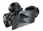
Initially it a was pencil, some graph paper and a calculator. Then the rough prototype shown at the top of this thread was built and tested. After that a Solidworks drawing was made.

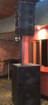
I then paid for the CNC programing and another porotype was constructed out of MDF … - some modifications were made and then 17 boxes were cut out of plywood …

I of course did a lot of modelling with different 8" drivers - Max SPL, Xmax, box size and tuning etc. I also tested some arrays of the HF driver and horn.
 
Last edited:
  • Like
Reactions: alastair mcewan
Where did you source the flywear for these awesome boxes..
I am going to do some 2x10 / 1.4 " flyable boxes
great work Peter
 
Where did you source the flywear for these awesome boxes..
I am going to do some 2x10 / 1.4 " flyable boxes
great work Peter

The same place were a lot of the big names get their stuff – - China. I think initially through www.made-in-china.com/

If you are planning on making a 2 x 10 / 1.4" line-array be careful of your horizontal dispersion and getting the acoustic centres of the 10's close enough to behave as they should ... and of course you will need an appropriate HF line-array horn/wave guide.
 
If you are planning on making a 2 x 10 / 1.4" line-array be careful of your horizontal dispersion and getting the acoustic centres of the 10's close enough to behave as they should ... and of course you will need an appropriate HF line-array horn/wave guide.

yep, Meyersound has this arrangement on some of their products


Attachments

  • mina.jpg
    mina.jpg
    20.1 KB · Views: 128
yep, Meyersound has this arrangement on some of their products

Meyer’s configuration is interesting. I have tried a few experiment with this configuration; it’s difficult to get good horizontal pattern control without overlapping frequency bands and it’s easy to have issues associated with the cavity between the 10s and the horn flare … look carefully at what Meyer did.

This is what Adamson say about their new S10 (2 x 10” and horn)

“Low-mid frequency lobing is a common side-effect of traditional 2-way enclosures. To solve this problem, Adamson has introduced Controlled Summation Technology, which reduces the spacing between mid-frequency sources by outwardly splaying the drivers and using overlap control between mid-frequency and high frequency sources to suppress the interference normally associated with this type of design. Doing this also allows the high frequency sound chamber to retain its exit size, ensuring that it retains its superior directivity control”

Have a look at RCF’s HDL20 (2 x 10” and horn) horizontal directivity around 500-800Hz
http://www.rcf.it/c/document_library...DLFE-21711.pdf

… and also have a look at how db Technologies tried to solve the problem with their new VIO integrating the 10s output into the HF horn flare https://www.youtube.com/watch?v=eD0liUcfoVc

To keep the pattern control precise Martin’s MLA Compact design used separate horn for the MF and HF horns. To solve the associated horizontal directivity problems at the crossover point associated with parallax timing off-set, Martin used “VanishingPoint” high slop FIR filters … this is the approach I used in my 8” + horn design. It also used a horizontal phase plug on the 8” similar to Nexo’s Geo designs to improve vertical array behaviour.

“The GEO S-8 array element uses 8 inch cone woofers and 1 inch compression drivers, so we need to operate the woofer up to at least 1200 Hz. However, we can’t expect to get eight inch woofers closer than 10 inches on center. This means that they will be a full wavelength apart at 1300 Hz. Adjacent woofers will start to become separate sources at 325 Hz (1/4 wavelength spacing) and will be developing individual lobes at 625 Hz: far too low to cross over into the compression driver. A relatively simple phase plug on each cone, however, can narrow the dispersion in the coupling plane and widen it in the non-coupling plane, enabling adjacent woofers to couple effectively at much higher frequencies. The blue trace above is dispersion vs. frequency for an 8 inch cone woofer, with the patented GEO phase plug. Without the device (red trace) the pattern becomes too wide at crossover. With the device adjacent woofers can couple effectively at 2000 Hz which is a comfortable crossover frequency for a 1 inch compression driver.”
 
winch.jpg

I have built some mini winch up Line-Array towers, they are about 11 ft tall and attach to the back of the double 21" subs. The base of the sub is big enough to make this stable. The towers should also be perfect for the DIY double 12s.
 

Attachments

  • ASH line towers.jpg
    ASH line towers.jpg
    450.6 KB · Views: 262
Last edited:
Peter, is the phase plug sculpted in the back to match the woofer's shape? Or is it a flat piece just bolted on and the "butterfly" shape makes it work?

I've often wondered about this style of phase plug.

Awesome work btw, as usual!

It matches the shape of the woofer, in this case the woofer has an inverted dust cap. phase plug.jpg
 
Wow. Did you build it? or is that offered by the manufacturer?

I did what so many manufactures are doing; sourced it and the fly-ware from China. Neither were exactly what I needed and had to be slightly modified. The phase plug was designed for a 200 watt B&C speaker, I used a 300 watt 18sound. I believe B&C has an almost exact OEM version of this driver however it was not available to me.

These were the two things I needed to make the project viable.
 
Hi Peter,
I just joined after noticing your project, very cool indeed. Was wondering what results you had testing different AMT's? For my studio monitors this was my first preference but subsequent to smacking a cymbal and listening to playback the only driver than could resolve the dynamics of live was a compression driver. Tried some ribbons and some AMT's there are probably different results from different AMT's so am curious if there is one out there with the dynamics of a compression driver.
What software did you use to calculate your FIR's and what do you use to analyze response of a new venue?
Thanks,
Mick

For me Beyma’s new TLP200H made this project possible. It’s 104 dB w/m and takes 120 w continuous. Its efficiency is about 3 - 6 dB down on a typical 1” compression driver but it takes twice the power and can operate down to 1KHz.

Given that an ATM is a true line source I believe these drivers combine better with fewer losses that most of your typical compression drivers on line-forming horns/lens.
`
The TPL200H seems to be quite happy keeping up with the 8” driver. Drums sound amazingly real, more so than anything else I have heard. I should also say that this system was designed for sound quality over everything else. If I wanted SPL I would have used a BMS 4507ND.

To tune it I use Sysune integrated with a Lake LM26 … I fine-tuned the latest settings by voicing the system with a measurement mic until it sound exactly like my voice +/- 0. Much more revealing than a vocal mic … testing these settings tonight :)

I also use TDA EQ, it give you an insight into things in the time domain that you don’t see with Systune or Smaart.

https://www.youtube.com/watch?v=-LLYkGj7Zbk
 
Hello from Finland

Peter

I have been following many of your projects with great interest. I just got idea of how to use bunch of unused components occupying my shelves. I have enough of JBL 2425/6 compression drivers + RCF 8-inch cone drivers for 6+6 or 8+8 setup. Just have to get the horns and hours of woodwork . . .

I do have amps and some processors - so investment for this project would be economically small, but time consuming.

One question of your finished project. Is the horizontal output symmetrical - or do you stack one side "upside down" ? So are the horns on same side of woofers on both sides of the stage?

Thank you for delivering all this wonderful information to everybody.
 
@Helge

They are performing very well. We used them on the weekend for a very important show. Typically they only use d&b, L-Acoustics and Meyer in that venue. At sound check they seemed very impressed but I have not had a report back about the show yet.

In terms of SPL, the TPL200H has more output than a single 8” driver. With a line-array it’s a different. I think it’s a good match in this case, but I have not had an opportunity to really see what it can do.

It also depends on how many boxes in the array and what crossover frequency you select. In this case I’m crossing them quite low to ensure good pattern control.

@ Timo –

It’s a single 8” and horn. I made all the boxes the same but the fly-ware makes it very easy to invert one array so if needed the array can be symmetrical.

The problem using a dual 8”, with an 8” driver either side of the horn is maintaining a good horizontal pattern, I can get too narrow because of the spacing of the 8” drivers has a dipole action.

The problem with a single 8” and horn is the parallax error that causes a time off-set as you move off axis and the resulting radiation errors. If you can space the horn and LF driver so they are less than about half a wavelength at the crossover frequency and use very high slope crossover the radiation error is minimal.

You will also need to use a wave guide (plus horn flare) like this; http://www.eighteensound.it/Portals/0/PDFs/XG10.PDF with your 2425's
 
I'm sure the paraline lens works just fine - There are quite a few different options available.

All of these devices take a point source and convert it to a line source. The V-Dosc wave guide was more or less the first. The others were designed to do the same without infringing on the original patent, but I'm not sure which is the best.
 
I've just come across this thread - nice work. I can confirm that Beyma's TPL-xxx drivers are absolutely sensational, with the caveats of low maximum output compared with conventional compression drivers. They are also very tough, as a friend proved by doing the sound check with them crossed over at 120Hz by mistake! Still working beautifully.
I have been looking for the DPD phase plugs for ages - could I trouble you for the manufacturer's link please.
 
The TPL150H was a little down on SPL but the new TPL200H add 2 dB more efficiency and another 2dB in power handling so it was very close to your typical 1” compression driver in SPL capabilities, certainly enough to keep up with a 8” low mid.

The phase plug was sourced from China. It did need some modification to suit the 8” driver I used. I believe the phase plug was designed to suit a B&C driver. - https://jsoundaudio.en.ec21.com/line array TPL200.jpg