Help me understand system limiting- setting it

Re: Help me understand system limiting- setting it

Hello all. I'm late arriving here. Three thoughts ...

However, the reason for peak limiting is to prevent over excursion.

This is a common myth, I'm afraid; signal peaks have little to do with driver excursion. A peak implies a high current for a short time which implies high driver acceleration for a short time. High acceleration for a short time will have little effect on displacement.

The main factor in excursion is low frequency content. For example, imagine a 1kHz sine wave just under a peak limiter threshold with 1 volt crests being fed to a driver, and imagine that this causes an excursion of 1mm. Now give it a 500Hz sine wave instead (an octave lower) still with 1V crests, and you'll find (all else being equal) that the excursion is 4mm. Go to 250Hz, and the excursion is 16mm. This is why drivers often have different power ratings for different low frequency limits.

60 milliseconds is not a slow attack. Attack time for thermal limiting should be seconds.

It depends on the frequency of the bandpass. If the attack time is too fast, it'll mess up the waveform but if it's too slow, the driver will fry before the limiter clamps down. It's typical to set the attack inversely proportionally to the lowest frequency in the bandpass.

I never understood attack and release values with out some reference to dB, i.e. dB/s or s/dB. With just time, no matter how hot the signal is, it's squashed in the same time. Seems this varies across the industry.

It's the time it takes to change gain by some amount, usually 10dB.

Nick
 
Last edited:
Re: Help me understand system limiting- setting it

Hello all. I'm late arriving here. Three thoughts ...
This is a common myth, I'm afraid; signal peaks have little to do with driver excursion. A peak implies a high current for a short time which implies high driver acceleration for a short time. High acceleration for a short time will have little effect on displacement.

Hello..... Signal peaks (transients) CAN mean a high excursion (or displacement). And..there was no mention of a specific frequency or frequency range. "High acceleration for a short time" is a "relative", pretty vague description. In Bennett's statement, he was referring to hard limiting (peak limiting) ...which can/would prevent over excursion. (but could cause other problems if not addressed)


The main factor in excursion is low frequency content. For example, imagine a 1kHz sine wave just under a peak limiter threshold with 1 volt crests being fed to a driver, and imagine that this causes an excursion of 1mm. Now give it a 500Hz sine wave instead (an octave lower) still with 1V crests, and you'll find (all else being equal) that the excursion is 4mm. Go to 250Hz, and the excursion is 16mm. This is why drivers often have different power ratings for different low frequency limits.

It depends on the frequency of the bandpass. If the attack time is too fast, it'll mess up the waveform but if it's too slow, the driver will fry before the limiter clamps down. It's typical to set the attack inversely proportionally to the lowest frequency in the bandpass.

It's the time it takes to change gain by some amount, usually 10dB.

Nick

In either case, damage to drivers could occur
Hammer
 
Last edited:
Re: Help me understand system limiting- setting it

Hi Charlie,

Signal peaks (transients) CAN mean a high excursion (or displacement). And..there was no mention of a specific frequency or frequency range. "High acceleration for a short time" is a "relative", pretty vague description. In Bennett's statement, he was referring to hard limiting (peak limiting) ...which can/would prevent over excursion. (but could cause other problems if not addressed)

With the numeric example I gave, I hoped to illustrate that no amount of hard (peak) limiting will prevent over-excursion because it ignores frequency. Take any waveform you want, lower it by an octave whilst keeping its amplitude (and peaks) unchanged and, all else being equal, excursion will quadruple. ("All else" pretty much will be equal for MF and HF drivers, but probably won't be for LF drivers where cabinet porting is involved.)

Determining maximum excursion from the waveform isn't trivial and can be unintuitive. It's possible, for example, to change excursion without changing frequency content by fiddling with phase, and it's possible to have two signals with the same frequency content where the one with lower peak amplitude causes greater excursion.

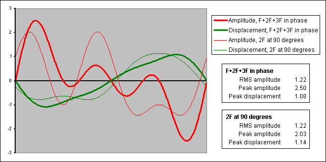
As an example of this, consider a signal containing three frequencies, F, 2*F, and 3*F all with peak amplitude 1V and all in phase. The RMS amplitude of the combined result is 1.22V RMS, the peak amplitude is 2.50V, and the peak displacement (in arbitrary units) is 1.08. Now, change only the phase of the 2*F component and shift it by 90 degrees. The RMS amplitude is unchanged, the peak amplitude is reduced to 2.03V, but the peak displacement is increased to 1.14.

On a graph, a single cycle looks like this:

excursion.png

Of course, peak power is a danger to drivers, but not because of excursion. The right way to protect against over-excursion is with an appropriate HPF plus an appropriate power limiter.

Nick
 
Re: Help me understand system limiting- setting it

Nick,

Perhaps I should have clarified and said "Since the only tool available to us to deal with driver excursion is a peak limiter, that is what they are used for". I am not aware of anyone offering sidechain EQ on their (modern) limiters, and certainly taking into account the phase characteristics of both the system and the filter set is something that probably only a high end manufacturer could address. I am not aware of any that currently address it properly, so I continue to set limiters based on worst case excursion at lowest frequency, which is fortunately helped somewhat by the high pass and box tuning.

Driver VC impedance rise is also a serious concern in excursion limiting, and I think only Nexo even attempts to address it.

P.S. Thank you for your (as always) excellent info. It's great to see you over here.
 
Re: Help me understand system limiting- setting it

I have a question concerning setting the attack and release times for peak limiters. I have seen a trend that lower frequency speakers have a slower attack time...and higher frequency speakers have a quicker attack time...Why? It may take lower frequency signals 10 to 100 times longer to complete a cycle...but why isn't everything set as quick as possible to detect the peak as soon as possible? As I am writing this, I think i may have thought of the answer...if a quick attack time is set on a low frequecny signal it will essentially square off the top of the waveform where as if it is set to attack after a full waveform develops the limiter will not square off the waveform, and reduce the entire cycle. Or does this have more to do with release times? Thinking out loud here.
 
Re: Help me understand system limiting- setting it

Hi Bennett,

Thanks for the welcome.

"If the only tool you have is a hammer ..."? That's fine. What I was shooting at was the idea that excursion follows applied voltage (or current) so that a large peak represents high excursion and can be controlled with a peak limiter. A peak limiter is fine if you need to limit peak power (for example, if you're lucky enough to be able to use the same big amplifiers on every bandpass), but otherwise it's the wrong tool.

I don't know how many manufacturers of active boxes are modelling excursion using their built-in DSP, but it sounds like a very good idea that should allow them to extract the maximum performance from the components. Doing excursion modelling in a general-purpose processor is probably out, though doing it in an amplifier (that can readily sense driver current) might be practicable with a minimum of user parameters. Probably too tweaky for most users, though.

In most cases, I think the best plan is to use the manufacturer's AES power rating, assuming it's legit. This should (according to AES-2) include the lower frequency limit of the frequency decade that was used for the test. A decent hi-pass filter at or above that limit plus a power (RMS) limiter usually works well.

Using a side-chain filter prior to a peak limiter where the filter models the rising excursion with reducing frequency is an interesting idea. I think the scheme could work if fed with sine waves but, if I understand correctly, it can't accurately model excursion for real signals that have multiple frequency components.

Anyway, I hope the main thing to take away from this is: signal peak != excursion peak.

Nick
 
Re: Help me understand system limiting- setting it

Using a side-chain filter prior to a peak limiter where the filter models the rising excursion with reducing frequency is an interesting idea. I think the scheme could work if fed with sine waves but, if I understand correctly, it can't accurately model excursion for real signals that have multiple frequency components.

Nick,

What if you applied a HPF and LPF to the side chain to appropriately model the acoustic phase of the driver in the box (somehow ignoring port contributions in LF drivers), and then applied parametric boosts at least on either side of the impedance maximum to account for excursion peaks at those frequencies? Then your limiter might be seeing a final phase nearly equivalent to that in the air. I think if you can get within 3dB that would be plenty close, especially considering that nobody's going to give you an amplifier that big anyway.

I think power limiting is much less interesting, although a sidechain EQ could help there as well but I think you'd want to do it without the phase shift?
 
Re: Help me understand system limiting- setting it

Hi David,

I have a question concerning setting the attack and release times for peak limiters. I have seen a trend that lower frequency speakers have a slower attack time...and higher frequency speakers have a quicker attack time...Why?

When limiting the power applied to a driver, it's usual as you say to use slower attack times for lower bandpasses. The attack time is often made inversely-proportional to the lowest frequency in the bandpass. This is related to the thermal time constant of the driver (that's how quickly it heats up and cools down) and, as you say, the length of a cycle. If the attack is too slow, the driver will have cooked before the limiter acts but, if it's too fast, it will distort the waveform.

It may take lower frequency signals 10 to 100 times longer to complete a cycle...but why isn't everything set as quick as possible to detect the peak as soon as possible?
There may be a terminology issue here. A "peak limiter" can mean a limiter (i.e. a compressor with a high or infinite ratio) with a detector that looks at peak signal level. When the detector sees levels over threshold, it starts to gradually ramp down the gain at the attack rate. When the detector sees the signal go back below threshold (and after any hold time has expired), the gain is ramped back up at the release rate. You're thinking of "peak limiter" in the sense of hard-limiting with zero overshoot. That can be done with a limiter as above plus a clipper to clip off the overshoot until the limiter has had chance to reduce the gain. The brief clipping is usually inaudible. In the digital world, it can also be done by having the detector "look ahead" by delaying the main signal so that the limiter can start reducing gain before the signal goes over-threshold.

Why are you concerned about peaks? Do you have an amplifier whose peak power is much larger than the driver can handle? If so, fair enough. If not, the amplifier voltage rails provide a pretty good clipper, and what you really need may be an RMS limiter. Any driver can be relied upon to handle short peaks at least 6dB above its power rating (i.e. four times power), and quite probably higher.

Nick
 
Re: Help me understand system limiting- setting it

Hi Bennett,

What if you applied a HPF and LPF to the side chain to appropriately model the acoustic phase of the driver in the box (somehow ignoring port contributions in LF drivers), and then applied parametric boosts at least on either side of the impedance maximum to account for excursion peaks at those frequencies? Then your limiter might be seeing a final phase nearly equivalent to that in the air. I think if you can get within 3dB that would be plenty close, especially considering that nobody's going to give you an amplifier that big anyway.

Not sure I follow. I haven't researched this properly, but I can't see how any conventional filtering in the side-chain could cause the limiter to accurately track excursion. Random example from a simple model: signal with just frequency F at some amplitude causes excursion X. Add frequency 3*F at equal amplitude in phase, and excursion goes down considerably below X. Switch frequency 3*F to be 180 degrees from F, and excursion goes up considerably above X.

Would it matter in practice? Would a limiter with a filtered side-chain be "good enough"? I don't know (but I'll stick to HPF + RMS limiter for now!). But if anyone wants a project ...!

Nick
 
Re: Help me understand system limiting- setting it

Hey Nick,

Sorry, it is obviously me who wasn't following! What you were saying didn't really sink in, but I see now that there is no conventional processing that will allow excursion modeling. Too bad someone doesn't build that into a DSP, it would be nice to get the extra performance. Since it's not too hard to have a handle on heat, if one had a reasonably good (slightly conservative) excursion limiter it would be possible to build a practically unkillable box without the penalty we currently pay. Add VC heat modeling that affects peak limiter threshold as well as some dynamic EQ and you could really beat the hell out of a PA and not even know it.

Naturally all my tunings have protective high pass filters! I really need to get an impedance meter, but I don't tune that many passive boxes and I usually don't have the time to really take them to the bleeding edge.
 
Re: Help me understand system limiting- setting it

The only thing that I would add is that you should be careful so that you aren't in limit the entire time. Although limit can protect your drivers from spikes a system that is in limit the entire time can possibly damaging your drivers. This happens when your complex sine waves of the "push-pull" in your divers become square waves causing the drivers to not travel their intended distances.

This actually isn't true. Even square waves applied to speakers diaphragms cause work to be performed, i.e. cone motion. In fact, the motion is the same as sine waves into the driver. That's why it's possible to cause over-excursion with clip amps as well as over-heating because the 'flat' portion of the waveform is still causing the VC to move in a direction.

The only thing that I would add is that you should be careful so that you aren't in limit the entire time. Although limit can protect your drivers from spikes a system that is in limit the entire time can possibly damaging your drivers.

For many systems this is true. I will say, however, with modern processors and 2 stage 'look ahead' limiters, I've seen rigs hammered hard into full limiting for extended periods without damage. If both correct rms and peak limiting are in place, you should be able to abuse a system to it's fullest without damage, that's the point right? Of course, it may sound gawd awful, but the speakers shouldn't 'get hurt' ;)

Greg
 
Re: Help me understand system limiting- setting it

BJ,

60 milliseconds is not a slow attack. Attack time for thermal limiting should be seconds. The DRPA does not have attack times of this magnitude available. The DRPA cannot do thermal limiting without destroying the output capability of the speaker.

Im just starting to tackle this with Itech6000s and JBL STX828s and 835s. JBL supplied me with data for a good starting point on xover, delay and PEQ settings but no RMS or peak voltage limiter settings - Im happy to share with anyone thats interested.

The STX828s are rated at 2000/4000/8000 in parallel mode. From what Im reading I may want to start with an RMS limiter set to 1000 watts to avoid power compression and then tweak as I use the system?
As far as peak voltage, I have seen threads that suggest 113v for drivers listed at 1600/3200/6400 - does that mean I can go higher than that? Do I want to?

The STX835s are rated at 1600/3200/6400 in full range and the low section is rated the same in biamp mode with the high section rated at 350/700/1400. Would 800 watts be a good starting point for full range or biamp, low? Following the same logic, 175watts for bi-amp, high? How do I determine the voltage setting for the peak voltage limiter?

As far as attack & release, the default settings for the Itech RMS limiter in Audio Architect is an attack of 4 seconds and a release of 6 seconds which seems to follow Bennett's suggestion. Any comments on that? What about attack and release for the peak voltage limiter?

Thanks!
 
Re: Help me understand system limiting- setting it

Im just starting to tackle this with Itech6000s and JBL STX828s and 835s. JBL supplied me with data for a good starting point on xover, delay and PEQ settings but no RMS or peak voltage limiter settings - Im happy to share with anyone thats interested.

The STX828s are rated at 2000/4000/8000 in parallel mode. From what Im reading I may want to start with an RMS limiter set to 1000 watts to avoid power compression and then tweak as I use the system?
As far as peak voltage, I have seen threads that suggest 113v for drivers listed at 1600/3200/6400 - does that mean I can go higher than that? Do I want to?

The STX835s are rated at 1600/3200/6400 in full range and the low section is rated the same in biamp mode with the high section rated at 350/700/1400. Would 800 watts be a good starting point for full range or biamp, low? Following the same logic, 175watts for bi-amp, high? How do I determine the voltage setting for the peak voltage limiter?

As far as attack & release, the default settings for the Itech RMS limiter in Audio Architect is an attack of 4 seconds and a release of 6 seconds which seems to follow Bennett's suggestion. Any comments on that? What about attack and release for the peak voltage limiter?

Thanks!

I'll let Ivan or some one else address the peak voltage limiters. For the RMS power limiters I like them to keep mostly out of power compression. Using pink noise (and hearing protection) you can drive a sub, LF or MF transducer until it stops getting louder, the trick is to find the point at which adding 3dB more signal does not get you 3dB more acoustic output. After a few more minutes you may find the level dropping a bit more. Measure output voltage, measure impedance, and use Ohm's law to determine Watts. That's the Reader's Digest version. You will be surprised at how low the number might seem if you were thinking of 1000W.

You will note that I didn't put the HF in this test method. I've yet to find a good way to this in situ that doesn't become an unintentionally destructive test. I recall some discussion on PSW about the relative merits of RMS limiting in the HF but don't recall a consensus.

Perhaps Bennett can add more to the discussion, since he peddles transducers... ;)
 
Re: Help me understand system limiting- setting it

I believe accurately modeling (or directly measuring) excursion and voice coil temperature is realizable but not a lot of people are doing it (yet). It requires a high level of integration between the driver, enclosure, amplifier, and processor. At this point, for most users and manufacturers, the money spent on fancy processing may better be spent on a more powerful rig that does not need to be run so close to its limits to achieve the required acoustic output. For now, properly applied peak voltage limiting, possibly combined with average power or RMS voltage limiting and a bit of care by the person at the controls does an adequate job.

People want different things from limiting. (What problem are we trying to solve?) Personally, I want it to protect the speakers from accidents such as dropped mics, bad phantom power connections, and acoustic feedback events. I also can understand the desire to protect low frequency drivers from prolonged (thermal) overload, but I don't run my hobbyist rig that hard. Many folks seem to view the limiters as a system-wide compressor to be used for artistic effect. I say if you want to crush the whole program, which I generally don't, do it upstream with the right tools.

One practical note on setting up limiters: After going through the wild-ass guesses and subsequent math to come up with the settings I often hook up a signal generator and a 'scope (without speakers) to verify that I have the settings I think I do. There are just too many ways to mess it up, especially with a new processor and control program. This needs a little thought and test signal design if separate peak and average limiters are employed. And if the amplifiers sense current as part of their limiting strategy a dummy load must be used for that part.

--Frank
 
Re: Help me understand system limiting- setting it

I'll let Ivan or some one else address the peak voltage limiters. For the RMS power limiters I like them to keep mostly out of power compression. Using pink noise (and hearing protection) you can drive a sub, LF or MF transducer until it stops getting louder, the trick is to find the point at which adding 3dB more signal does not get you 3dB more acoustic output. After a few more minutes you may find the level dropping a bit more. Measure output voltage, measure impedance, and use Ohm's law to determine Watts. That's the Reader's Digest version. You will be surprised at how low the number might seem if you were thinking of 1000W.
Tim,

I see two problems problem with your method, one is measuring voltage with a pink noise source, and the other is the noise source, pink noise has a crest factor of 12 dB, while some EDM (electronic dance music) has a crest factor of only 3 dB in the LF, eight times more average power than pink noise. To be safe from that kind of "music", average ("rms") power should be limited to about half to 3/4 the AES 1984 rating (there now is an AES 2012 rating using 12 dB crest factor pink noise...), which uses a pink noise signal with a crest factor of 6 dB. You could use a sine wave at Fb (box tuning, impedance minima) with your method to be safe.

Peak voltage ideally would be set with a frequency dependent curve based on driver excursion, but in general twice the AES 1984 rating will be in the safe zone, though won't address distortion. That said, distortion makes music "sound louder", so letting peaks distort may satisfy the customer better...
 
Re: Help me understand system limiting- setting it

Tim,

I see two problems problem with your method, one is measuring voltage with a pink noise source, and the other is the noise source, pink noise has a crest factor of 12 dB, while some EDM (electronic dance music) has a crest factor of only 3 dB in the LF, eight times more average power than pink noise. To be safe from that kind of "music", average ("rms") power should be limited to about half to 3/4 the AES 1984 rating (there now is an AES 2012 rating using 12 dB crest factor pink noise...), which uses a pink noise signal with a crest factor of 6 dB. You could use a sine wave at Fb (box tuning, impedance minima) with your method to be safe.

Peak voltage ideally would be set with a frequency dependent curve based on driver excursion, but in general twice the AES 1984 rating will be in the safe zone, though won't address distortion. That said, distortion makes music "sound louder", so letting peaks distort may satisfy the customer better...

Agreed

My "go to" limiter settings for EDM type music is 1/2 the continuous wattage rating.

This has worked very well for me. Granted, often times the subs are in limiting during the show-but when you hard limit a sine wave nobody notices :)

The fastest/easiest way is to figure out the voltage for the continuous rating (square root of (wattage x impedance)), then multiply by 0.707. Now they have a target.

Use a sine wave generator in the freq band of interest and turn it up to a decent level above the desired target. Then simply dial back the limiter threshold until the voltage gets to the target.

DO NOT have loudspeakers hooked up when you do this. Unless you want to replace them.
 
Re: Help me understand system limiting- setting it

Use a sine wave generator in the freq band of interest and turn it up to a decent level above the desired target. Then simply dial back the limiter threshold until the voltage gets to the target.

DO NOT have loudspeakers hooked up when you do this. Unless you want to replace them.
But do use a load resistor when you do this, as some amps limiters respond differently with no load. That said, the output voltage is usually less when loaded, so if you dial it in, then add the speaker load, you may only have to adjust slightly.
 
Re: Help me understand system limiting- setting it

But do use a load resistor when you do this, as some amps limiters respond differently with no load. That said, the output voltage is usually less when loaded, so if you dial it in, then add the speaker load, you may only have to adjust slightly.
Agreed, but with modern amps able to produce such high power, a normal load resistor may not be able to dissapate the power.

Also with modern amps that are rated in "burst" power, they may not be able to produce enough voltage (when loaded down) long enough to measure and adjust.

I have not done it, but would "argue" that the difference is voltage is not enough to worry about. Usually just a few parts of a dB.
 
Re: Help me understand system limiting- setting it

Agreed, but with modern amps able to produce such high power, a normal load resistor may not be able to dissapate the power.

Also with modern amps that are rated in "burst" power, they may not be able to produce enough voltage (when loaded down) long enough to measure and adjust.
True, even the better modern amps can not last more than a few seconds with high power sine waves. I use my household 1500 watt oil filled 120v heater elements for load resistors, they are about 9.6 ohms between two elements, so I just add them in parallel and switch off elements to arrive at the impedance needed. Four can handle 6000 watts indefinitely, but I haven't tested any amps that do much more than "tickle" the load.
 
Re: Help me understand system limiting- setting it

True, even the better modern amps can not last more than a few seconds with high power sine waves. I use my household 1500 watt oil filled 120v heater elements for load resistors, they are about 9.6 ohms between two elements, so I just add them in parallel and switch off elements to arrive at the impedance needed. Four can handle 6000 watts indefinitely, but I haven't tested any amps that do much more than "tickle" the load.
I have mine just in water-in paint cans with holes in the top-to keep it from exploding and hurting me.

I have found the resistance can vary a fair bit. I took an ohm meter to home depot and measured every one until I got some that were between 8 and 9 ohms.

Close enough for what I am doing.