New DIY Mid High (90deg) - AKA PM90

Hi guys,
Peter, thank you for the inspiration starting of this journey of designing a derivative based on yours and some of my own findings/research.
I've designed a version using two 15" (15NW76) in a sealed enclosure with the drivers facing the end panels through a short horn like adapter.
[FONT=&amp]I find it imperative to reduce the vertical source size in a MTM. Assuming we have DSP at our disposal, the sealed alignment using two large radiators with good excursion capabilities yields quite good low frequency efficiency (not unprocessed sensitivity though!). It is capable of 135db max spl down to 80hz 24dbLR, when applied eq, which is around the limit of the high frequency driver anyway. It's displacement limited, so those 135dB does not pull lots of power causing power compression and overheating. Unlike, the vented alignment having port noise and very delicate rear volume requirements, the LF output of the sealed alignment decreases at 12db/octave and can be adjusted as low as reasonable as long as one keeps an eye on the excursion below natural cutoff.[/FONT]

Link to Don B. Keele's paper (part 1) on Linear phase crossovers and symmetric driver arrays (see MTM):
http://www.xlrtechs.com/dbkeele.com/PDF/Keele%20(2007-09%20AES%20Preprint)-%20Linear%20Phase%20Digital%20Crossover%20Flters%20Part%201.pdf

Here is a sketchup pic. The large cutout in the rear panel is to accommodate an amp module. The entire side and rear is made from a single piece of kerfed 18mm birch ply, to approach a cylindrical enclosure for good damping and minimized wall flex. The front panel is removable to access the 15"s and to allow different HF horn/driver combinations

I too considered every imaginable layout possible and ultimately arrived at this fairly simpel one. There is a lot of ways do such a speaker but only a few designs seems to obtain a good balance of requirements. This is just me trying to make anyone who is looking into designing their own version, avoid being blinded by a single design or idea
Best regards Fred

Hi Frederik,

Love your design, its very similar in many ways to my double 14" design which is also sealed. Its also similar to Seeburg's K24, except they have ported the the LF and I don't like how the 12" speakers have 2 entry point into the small horn. (see the link below)

If you look carefully at their directivity plot, you can see the advantage of getting the crossover point a bit lower if your HF driver can cope with the extra load.

http://www.seeburg.net/download_get...06-Datasheets/K-Series/K24_Datasheet_engl.pdf

My idea for the dual 10" or 12" was very similar to your design and the K24. I was going to port it like the K24 to get a bit more LF.

Here is the frequency response of my double 14" on axis, at 45 degree horizontal and 20 degrees vertical ... ignore the lumps and bumps below about 250hz, there were some ground reflections etc. and I just did a quick measurement to check the directivity around the crossover at 650hz.

dbl 14 directivity.jpg
 
Hi Peter, appreciate your approval a lot!
I'm surprised i haven't come by the K24, it's almost exactly the same! It's an interesting bandpass/phaseplug solution they have found. I'm curious as to have well it reduces the path length differences. If you consider the ray like wave propagation I'm guessing the distance from each entry point to the front lip is the same. This was a major concern when designing an aperture "smaller" than the initial source. Compared to the simple offset driver layout, where the compression itself provides the "waveguide", and therefor in theory will have a slower decay time or subjective "smearing", the horn like layout should theoretically have a very good impulse response with little smearing but higher HOMs, reflections and adiabatic distortion. I'm still not certain about this decision and found it hard to quantify. Ultimately, I went with my intuition based on my knowledge of the various kind of distortion and their audible significance.

You are absolutely right on their decision on crossover point. My design (M30) has almost exactly the same vertical dimensions but uses a much broader crossover slope (per Keele), but also centered quite high. Interaction is very wide from 550hz (the lowmid critical frequency to 50 degrees) to 1500hz (the HF horn critical frequency). This restores the coverage of the HF horn and prevents the lowmid from collapsing, manifesting in constant directivity. You could probably achieve this with low order passive crossover too if you are willing to accept some phase wrapping. The K24 and my M30 both are naturally time-aligned, and can be run passive from that perspective. The sensitivity is not at all flat however.

I believe your plots are an amazing prove to how efficiently constant directivity can be obtained in such a relatively small package. You've done an amazing job Peter.

I'm surprised how low you operate yours. What is the natural resonance frequency?

Best regards Fred
 
I'm surprised how low you operate yours. What is the natural resonance frequency?

Best regards Fred

There was a double 18" sub included in the measurement ... sorry I forgot to mention that :-). The double 14 was crossed at 80 Hz and then at 630 Hz. In both cases its acoustically a 24 dB LR function/slope. The 80 Hz crossover is a 12 dB natural acoustic roll off EQ-ed to a 12 dB Butterworth shape combined with a 12 dB Butterworth electrical filter to produce a 24 dB LR roll off.

The 630 Hz is linear phase and there is quite a bit of phase manipulation with all-pass filters to get the end result.

Peter

As a point of education, are all second order roll offs from cabinets designs essentially the equivalent butterworth filter?
 
Sounds like a very elegant way to go about the lower band and crossover. I have come to love the sealed enclosure for this kind of freedom in various venues and applications. You can run them quite low for critical listening at low levels or run them harder with a higher crossover outdoors for instans.
I've had quite excellent results on and off-axis with the phase response using these higher fs low-order crossovers. It makes the lowmid design more delicate with regards to well behaved upper roll-off however.
I think i will have a go with your lowmid highpass method though!

What are the dimensions on your double 14? I'm also curious as to how you did the 14-baffle and internal bracing.

Fred
 
As a point of education, are all second order roll offs from cabinets designs essentially the equivalent butterworth filter?

The roll off is 12 dB but the shape probably will not match a Butterworth especially in this case where the LF section is more or less a 4th order band pass tuned around 500Hz.

This tuning produces a peak of about 8-10 dB that has to be corrected, but you do get more SPL and in this case the pattern control I wanted because of the the location of the two LF exits.

I EQ-ed it flat with the Butterworth shape roll off so that when I applied another 12 dB Butterworth (electrical crossover) I ended up with a 24 dB LR.

In practice I just took my best guess, added a 12 dB Butt electrical filter and fine tuned the end result to 24 dB LR
 
Sounds like a very elegant way to go about the lower band and crossover. I have come to love the sealed enclosure for this kind of freedom in various venues and applications. You can run them quite low for critical listening at low levels or run them harder with a higher crossover outdoors for instans.
I've had quite excellent results on and off-axis with the phase response using these higher fs low-order crossovers. It makes the lowmid design more delicate with regards to well behaved upper roll-off however.
I think i will have a go with your lowmid highpass method though!

What are the dimensions on your double 14? I'm also curious as to how you did the 14-baffle and internal bracing.

Fred

The double 14 is 920 mm high x 500 mm deep x 410mm wide. It can still be pole mounted - just. I don't think it goes any louder than the double 12 design but because its bigger there was more freedom to archive slightly better acoustic performance. The main issue with this design is the HF horn is not available to purchase ... but it is VERY good horn.

http://data.mecheng.adelaide.edu.au/...ation_2008.pdf
https://www.google.com/patents/US20080059132

The advantage of your short horn over the band pass design I used is that you can get 2 or 3 db more efficiency out of your design.

Initially I started experiment with a design similar Meyer's Leopard turn on its end, but I could not get it to work very well. The solution was to make separate band pass chambers for each of the 14" drivers and limit the width of the two exits.
 

Attachments

  • Meyer Leoard.jpg
    Meyer Leoard.jpg
    39.4 KB · Views: 229
Sounds like a very elegant way to go about the lower band and crossover. I have come to love the sealed enclosure for this kind of freedom in various venues and applications. You can run them quite low for critical listening at low levels or run them harder with a higher crossover outdoors for instans.
I've had quite excellent results on and off-axis with the phase response using these higher fs low-order crossovers. It makes the lowmid design more delicate with regards to well behaved upper roll-off however.
I think i will have a go with your lowmid highpass method though!

What are the dimensions on your double 14? I'm also curious as to how you did the 14-baffle and internal bracing.

Fred

Fred ... I had written a longer reply but it was marked as spam and deleted I think ... quick answer this time ... 920 mm H x 500 mm D x 410 mm W.

The advantage of your short horn is 2 - 3 db more efficiency compared to my band pass design.
 
Last edited:
Well, the horn was just a consequence of the source size requirement.
It does reduce power draw from just below it cutoff, and I guess that allows one to feed the less efficient lower band some more juice. Subjectively, I find that the heavier cones (compared to 12s), benefits from the "horn sound", which I attribute to adiabatic amplitude/pitch modulation, restoring the "fastness" found in smaller drivers. It does, however, also introduce some resonances to be dealt with in the DSP work.

These measures 716mm H x 450mm D x 450mm W (close to a perfect 1.6 Fibonacci ratio).

I suspect yours must benefit from a slightly lower tuning then

Fred
 
Last edited:
The original idea was to build something like Meyer's Leopard but rotate horn 90 degrees and then stand the box up. I found that if put each of the 14" drivers in their own chamber I got better results. I also needed to reduce the size of the LF drivers exit slots to control directivity better.

The problem with this design is the HF horn, its a wonderful horn (90 x 40 pattern) but not available for purchase.

A bit of info about it ...

http://data.mecheng.adelaide.edu.au...s/2008/preprint_morgans_optimization_2008.pdf
https://www.google.com/patents/US20080059132

These measures 716mm H x 450mm D x 450mm W (close to a perfect 1.6 Fibonacci ratio) ... you will have to paint your box GOLD :roll:
 

Attachments

  • Meyer Leoard.jpg
    Meyer Leoard.jpg
    39.4 KB · Views: 41
I found that if put each of the 14" drivers in their own chamber I got better results.

That's interesting..
I've found the opposing drivers, sharing a single chamber, to provide very good damping as they see a perfect impedance condition instead of a zero-velocity condition at the walls.

Fred


I found that if put each of the 14" drivers in their own chamber I got better results.

That's interesting..
I've found the opposing drivers, sharing a single chamber, to provide very good damping as they see a perfect impedance condition instead of a zero-velocity condition at the walls.

Fred

Hi Fred,

I should have said front chamber. The spacing of the two 14" drivers and HF horn sitting in the middle was causing problems. The volume of the chamber was also too big.

The drivers more or less share the same rear chamber. In your case you don't have a front chamber just two horn exits.
 
There are some final plans (pdf format and dwg), in terms of amps I'm using Powersoft K series. Some people have use the K series processing as well.

https://www.dropbox.com/s/h16is6mbji...rrent.pdf?dl=0
https://www.dropbox.com/s/xiuyecjy9k...rrent.dwg?dl=0

Hello Peter

First of all, thank you for all your hard work (and to anyone who has had input)

I am part of a group of friends from New Zealand who recently built 8 Othorn's (from Josh Ricci's current design) and are now looking at replacing the F1 Res2 clones with our own tops. My friend from Immersion Audio directed me to this thread as a possibility.

As an initial question, I was wondering if the data in the post I have quoted above, is the most recent/uptodate?

Regards

Aaron
 
I will be building my pair of these in the coming days and intend on cutting the back corners off for that extra smart look.

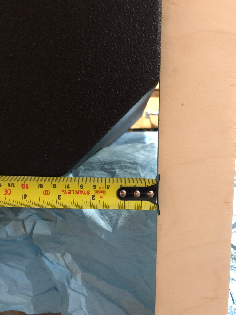
Peter, do you recall how much you took off ? And what are the limits here? I was planning on taking less than a 45 degree angle off and extending the cut a little further forward along the side of the cabinet.

I just made this cut a few weeks ago, and used a 45 degree angle. If I recall, the first thing that would hit on the inside was the tee nut for mounting the woofer. Also, if you already cut the access hole in the back, that may limit how deep you can go too.
03fb543b24eb031a07e4bd3024c55aa8.jpg