PMA - 60; New arrayable double 12 and horn.

Peter Morris

Senior
May 8, 2011
1,062
163
63
Australia
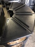
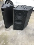
This is more or less an up date of my double 10 and horn design. It’s the same height and when multiple boxes are packed front to back it takes up about the same amount of truck space.

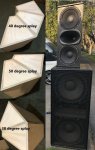
I often see people wanting use 2 or more boxes together to get more power, but they never array very well. The idea was to build a 60 x 40 degree box that could be tight packed and array with a lot less issues.

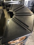
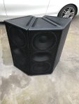
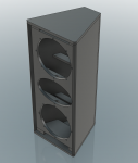
It’s a MTM design in a trapezoidal box. It has uneven angles - 25 degrees and 15 degrees. By doing this I can place 2 boxes side by side and have a total splay of 50 degrees with all the drivers very close together minimizing comb filtering issues.

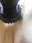
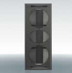
It’s necessary to have the other side at 15 degrees to get enough volume in the box. There is not enough room on the front of the box for reflex ports and they are located on the back, one on the top, and one on the bottom. They also work as a handle and add bracing to the walls.

You can array 3 or more boxes with 40 degree splay between the boxes.

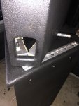
To get 25 degrees it’s necessary to machine the inside wall of the box on one side to fit the compression driver in.

It uses:

2 x B&C – 12HPL76 (I had these in stock and it was too difficult to get other drivers due to COVID-19)

1 x B&C DCX464

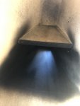
1 x Ciare PR614 horn

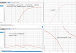
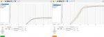
Processing – I’m using Linea Research ASC48 with LIR crossovers and FIR processing, but it should be very easy to get good results with other processors.

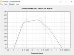
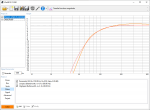
It designed to operate from 80Hz to 20K with a mid crossover frequency around 675Hz and 3250Hz for the VHF. In my case the mid crossover overlap by 100Hz (at the moment).

The plan is to build some MID-HI passive crossovers eventually ... more to come :)
 

Attachments

  • PMA 60-2.jpg
    PMA 60-2.jpg
    403.1 KB · Views: 558
Last edited:
Dang, and I just started ordering components for a double 10 and horn build...
Will be following this thread with great interest.
Thank you so much for sharing this and your other projects!
 
A couple more pictures - bottom rear port and top mounted fly track with internal aluminium bracing seen through top rear port (the box is upside down and its to be painted black)

... and DCX464 - very close fit.
 

Attachments

  • 7432D61E-A6B8-45CF-91B7-9E796E0418A9.jpeg
    7432D61E-A6B8-45CF-91B7-9E796E0418A9.jpeg
    1.2 MB · Views: 298
  • 9A10E76F-DA93-413C-A73D-9549697F8F10.jpeg
    9A10E76F-DA93-413C-A73D-9549697F8F10.jpeg
    1.8 MB · Views: 309
  • 36364BBC-B8F2-48F6-B2D9-4B310C828F9D.jpeg
    36364BBC-B8F2-48F6-B2D9-4B310C828F9D.jpeg
    1.2 MB · Views: 302
Last edited:
Hornresp plots - PM90/60 Vs PMA using the same driver and input signal.

Note the WinISD low frequency SIMs above assume 1/2 space. The Hornresp is in full space.

The cone displacement is without out a crossover.
 

Attachments

  • PM90-60 Vs PMA60.jpg
    PM90-60 Vs PMA60.jpg
    50.3 KB · Views: 198
  • xmax PM60 Vs PMA.jpg
    xmax PM60 Vs PMA.jpg
    43.8 KB · Views: 185
So, why build & lug 4 cabinets if 2 PM90s can do the job. 😉

These are smaller and lighter ... and you can array 2 or more boxes to get 110 - 120 degrees of coverage - perfect for front fill on a medium size rig or a small show that needs wide coverage :)

The idea behind the PM90 was the loudest best sounding box you could put on a stick, it was not deigned to array ... The idea with the PMA60 is a smallish arrayable box that can be used as one, two or three per side.

BUT most of all, a COVID-19 project while waiting for work to resume ...
 

Attachments

  • 624663A7-88C7-4594-BA09-01F5510B6240.jpeg
    624663A7-88C7-4594-BA09-01F5510B6240.jpeg
    2.3 MB · Views: 203
Last edited:
Again, nice work.
I personally don’t understand why a commercial manufacturer doesn’t offer something like this.
If you ever go «commercial», I’m up for six of these :)

Helge, Renkus used to. Maybe they still do... but as much as these boxes would work for me, promoters want to see line array looking things... regardless of performance. JBL VRX and company sorta poisoned the well...

That said, I have 6 old Renkus Trap 40/60's that are simply too heavy for me with out a three man crew. If I go back to live sound after covid, if I can't do it with 1 crew guy - I ain't doin it. These boxes look super cool to me as I expect they would be light enough to one guy to get onto scaffold.

I live in a very high wind locale and do a lot of wind sports event support. I'm a ground stacker. Anybody flying a rig here in either nutz or uncaring and well insured ;-)

6 of these might be perfect for me. I would build out of 12 mm VF euro ply.

I've been think about boxes exactly like this for a while. could these be done so 2 boxes arrayed would cover 80 degrees ?
 
  • Like
Reactions: Carl Klinkenborg
Looking good!
Out of curiosity, which 12" drivers would you have gone for in an ideal situation?
What about the FaitalPRO 12PR300 for example?
 
Last edited:
There are lots of drivers that will work in this box - these look very good, and I'm sure there are many more options.

Caire NDH12.4
FaitalPRO 12HF520
B&C 12NDL88
 

Attachments

  • 12 inch drivers.jpg
    12 inch drivers.jpg
    258.3 KB · Views: 157
  • Like
Reactions: Joris Wijgerde
Thanks a lot, Peter!

I was researching my own MTM solution using these exact B&C drivers(well, the newer 12NDL76). I was running into issues with matching a 24dB XO with a practical chamber volume. My brain totally forgot about wedging the darn thing! I also appreciate you sharing your approach to matching the 80hz 24db slope with the combo of the XO and PEQ.

Do you have a standard trick for showing a "perfect" BUT filter to match attenuation to? Are you just using some other driver/cab combo that has an even passband at the freq you're trying to model? Or does WinISD have some way to just show the curve of a filter on its own?

Thanks!
 
Last edited:
I spent a lot of time modelling things out in WinISD with 2x12NDL76 and I'm having a hard time making something with a reasonably sized port exit that isn't incredibly long and with a high port velocity. What kind of velocity values are you seeing in WinISD with your setup? Am I being overly concerned about velocity at or below the XO point? I thought the general idea was to stay below ~17m/s? Thanks
 
I have found that high port velocity tends to be of itself practically inaudible at the levels usually required to produce it. The main effects it produces are increased distortion and port compression (lower output). I always begin with a port area equal to the speaker's Sd (rarely possible) and work down from that size until the port fits the box keeping an eye on port resonances within the pass band and, of course, port velocity. Some of the car audio kids go to velocities approaching 40m/s, but with with their 10kW 12" drivers in boxes tuned to 12Hz, and their 20kW amps, they seem to get away with it...;)
Wherever possible I like to stay the right side of 10m/s even with ports properly flared on both ends to provide best symmetry of airflow to avoid port rectification.
 
  • Like
Reactions: Dave Eckblad
Thanks for sharing your experience Carl! That's helping me a great deal. But, one thing I'm still wondering is how Peter was able to build two ~8x8cm port openings that aren't as long as in the WinISD model I was working on to match his specs, with the same 12HPL76 data and same XO/PEQ settings, without hitting ~30m/s port vel. at the 80hz XO point.

Separate of that, I've been doing my own divergent work based off PM's asymmetrical cab design with the 12NDL76 and came up with this slightly taller version with ports to the front. I brought the tuning down a wee bit to move the port energy to just below the pass band region. This also helped me better match phase with a dual 18" reflex design I'm working on.
 

Attachments

  • 1601073791760.png
    1601073791760.png
    459.1 KB · Views: 136
  • 1601073910544.png
    1601073910544.png
    428.3 KB · Views: 137
  • 1601074235603.png
    1601074235603.png
    71 KB · Views: 136
Last edited:
Thanks for sharing your experience Carl! That's helping me a great deal. But, one thing I'm still wondering is how Peter was able to build two ~8x8cm port openings that aren't as long as in the WinISD model I was working on to match his specs, with the same 12HPL76 data and same XO/PEQ settings, without hitting ~30m/s port vel. at the 80hz XO point.

WinISD does not take in account any boundaries (like a wall). Those boundaries extend the port in that regard.
For a schelved port (like one for a sub) a factor of 0,7/0,8 could be taken in to account to find out the real lenght needed for a desired tuning (for winISD).
For example winISD says 30cm, that would translate to around 21-24cm, I can imagen that the port layout from this cab would even have a lower factor. However, real world testing will give you a final answer. In this case, start short and add extra length if needed.
 
  • Like
Reactions: Dave Eckblad
Thanks for sharing your experience Carl! That's helping me a great deal. But, one thing I'm still wondering is how Peter was able to build two ~8x8cm port openings that aren't as long as in the WinISD model I was working on to match his specs, with the same 12HPL76 data and same XO/PEQ settings, without hitting ~30m/s port vel. at the 80hz XO point.

Separate of that, I've been doing my own divergent work based off PM's asymmetrical cab design with the 12NDL76 and came up with this slightly taller version with ports to the front. I brought the tuning down a wee bit to move the port energy to just below the pass band region. This also helped me better match phase with a dual 18" reflex design I'm working on.

Yes the port velocity is a bit high, but the port is tapered with a large inlet so the air flow resistance is not as high as a "normal" straight port of that size. It also acts as a brace to strengthen the box without adding weight. In addition it exits at the back of the box so any noise from the port, or off of the rear of the speaker cone is reduced.

One of the aims of this design was to make it as small as possible - the same size as my double 10 if possible. To do that the horn actually overlaps the the 2 x 12" drivers. The 12's and horn even share the same mounting bolt hole at one point. It also minimizes the distance between the drivers to reduce any comb filtering and directivity problems.

Phase matching with my double 18's was not an issue as I can adjust it with all-pass filter or FIR filters as needed.
 
  • Like
Reactions: Dave Eckblad