FIR filters

Jim,

There is already a book load of information and links in this thread- check out post #'s 2, 90, 94, 111, 112, 114, 120, 143, 144 and write your own book!

Art "Titanium Cranium" Welter
 
Slightly off topic here, but could somebody suggest a good audio theory book or books to read in order to understand the conversations in this thread better? This could be the wrong place for such a question but i figure as anybody in this thread must have read such books, it is kind of the right place to ask as well.

If you're interested in the signal processing aspects, I would recommend Rick Lyons, Understanding Digital Signal Processing, is a pretty good introductory text, mentioned somewhere earlier in this thread.

edit: I almsot forgot, there are a ton of references in my AES powerpoint also.
http://www.cascadeacoustic.com/files/research/AES-PNW_Audio_Band_Test_and_Measurement.pdf
 
Last edited:
The following points came from post #120, by Phil Graham. (Tried to just quote that post, but the dang forum software quotes a different post.)


I must be missing something, because it appears points 2 and 5 are in opposition.

Point 2 seems to say a scrambled phase relationship reduces peak signal amplitude, which makes intuitive sense to me.
Point 5 seems to say that after phase correction is applied peak amplitude goes down. (Phase correction termed pre-warping, to undo the scrambled phase relationship) Shouldn't it go up? By the amount of reduction inherent in Point 2 ?

What am I missing? Thanks ! mark
  1. Any transient involves a wide range of frequency components (lows and highs) that must align with each other in a specific phase relationship to sum together in a way that gives rise to the rapid upward slope when viewing the amplitude versus time (i.e. like how your DAW displays a snare hit during a mix session).
  2. If you scramble the phase relationship between the various frequency components, the energy is still there at each frequency, but the arrivals are no longer coherently combining to give the rapid rise on the amplitude vs. time display. The net result is that the energy content is the same, but the peak amplitude of the signal is reduced.
  3. Since loudspeakers, which by their nature are bandpass devices that exist in a causal (i.e. time goes forward) universe, a loudspeaker is always going to alter the phase relationships of what comes out of it.
  4. We can quantify this alteration, and pre-warp the phase of the original signal to counteract the loudspeaker so that the loudspeaker's inherent limitations serve to re-align the phase back to the original desired signal.
  5. A side effect of the pre-warping on highly organized signals like transients is that the peak amplitude of the signal is usually reduced after pre-warping.
  6. Since amplifiers are usually constrained at high frequencies not by their ability to supply energy, but rather in their maximum voltage swing (i.e. amplitude), reducing the amplitude of the signal peak by pre-warping serves to open up some breathing room on the amplifier voltage swing, and therefore allows more possible peak output from an amplifier with a given voltage swing capability.

This diagram may help explain what Phil was talking about. (assuming an IIR crossover)
 

Attachments

  • FIR ans.jpg
    FIR ans.jpg
    85.9 KB · Views: 26
Thx Peter, would you say in your diagram, that 5 results in an increased, or reduced, peak signal ?
It sure looks like an increase to me.....?
which would seem to require an increase in amplifier voltage (in opposition to point 6.)
Still confused :)
 
Thx Peter, would you say in your diagram, that 5 results in an increased, or reduced, peak signal ?
It sure looks like an increase to me.....?
which would seem to require an increase in amplifier voltage (in opposition to point 6.)
Still confused :)

5 - As a result of the pre-conditioning the peak is reduced (2[SUP]nd[/SUP] diagram on the bottom); however once processed by the crossover (which has the opposite pre-conditioning / phase) the peak and wave shape is restored to match the input shape and peak (acoustic sum).

Note what Phil said - “a side effect of the pre-warping on highly organized signals [original signal] like transients is that the peak amplitude of the signal is usually reduced after pre-warping"

2 - Without the preconditioning the crossover phase response results in the low frequency and high frequency peaks not being aligned any more and the maximum amplitude is reduced.

This assumes that music signals are not random, rather “highly organized” and accordingly have their peaks aligned so to speak.

In terms of amplifier voltage – if the low and high frequency bits have the same amplitude, when they are aligned the voltage is double, this requires an amplifier of 4 times the powers; however the energy is the same … think in terms of the area under the curve(s).

In practice, if you get everything correct and preserve the transients and wave shape of the original signal your speaker will be able to reproduce a square wave ... see the very first post on the DIY :)
 
Last edited:
5 - As a result of the pre-conditioning the peak is reduced (2[SUP]nd[/SUP] diagram on the bottom); however once processed by the crossover (which has the opposite pre-conditioning / phase) the peak and wave shape is restored to match the input shape and peak (acoustic sum).

Note what Phil said - “a side effect of the pre-warping on highly organized signals [original signal] like transients is that the peak amplitude of the signal is usually reduced after pre-warping"

2 - Without the preconditioning the crossover phase response results in the low frequency and high frequency peaks not being aligned any more and the maximum amplitude is reduced.

This assumes that music signals are not random, rather “highly organized” and accordingly have their peaks aligned so to speak.

In terms of amplifier voltage – if the low and high frequency bits have the same amplitude, when they are aligned the voltage is double, this requires an amplifier of 4 times the powers; however the energy is the same … think in terms of the area under the curve(s).

In practice, if you get everything correct and preserve the transients and wave shape of the original signal your speaker will be able to reproduce a square wave ... see the very first post on the DIY :)

Hi Peter, sorry I've been slow at thanking you for your generous reply. I've been running experiments trying to fully digest what you and Phil have been explaining.

I think where I've been hung up, is that I've been looking at it from the perspective of a signal spit into mutichannel passbands, with 'prewarping on each of those channels. IOW, from the perspective of tuning the DIYs.
It's hard to see how any reduced load on an amp channel occurs in this case.

But if I think about 'prewarping' a signal going through a single amp channel to a speaker with a passive crossover in place, I can kinda make sense of a reduced amp load. I've tried comparing a dirac pulse (which I take to be a good example of a highly organized signal !), before and after some FIR adjustment that could represent plausible corrections for a passive speaker, and I do see a reduction in peak amplitude, post correction. So I'm hoping this is a valid understanding of what you guys are showing.

And yeah, I remembered the square wave response in post #1 quite well. It prompted me many months ago to get an o'scope and arb function generator, to keep learning. I've got some pretty decent looking square waves from the DIY, but not quite so good as yours ....yours look almost electrical !!


Hello Friends,

Some time ago I mentioned that it is very tricky to use FIRs to create a multi way system – to create a crossover.
Here is a solution – the software called C5.
The software is offering all the necessary management to operate the multi way system.
It allows to exploit a power of FIR to create an ideal crossover. Why ideal?
Because it incorporates correction for each particular band/way.

Take a look on some screen shoots and results.
The system „under test” was large PA with some bands already with acoustic filters (band pass). It is almost impossible to tune ordinary dsp for work with such system.
But the use of correction on each particular band allows to use very delicate crossover (LR24), get very low crossover’s group delay, as result, and possibility to correct it by sacrificing only 12 ms of latency.
APL has idea to create a 10 channel unit for DSP use – 4 channels with 8192 taps,
6 channels with 4096 taps. For use as 5 way DSP or 4 way DSP with master EQ on its input.

Please vote, is such unit necessary or not?
 

Attachments

  • 01_C5_main.png
    01_C5_main.png
    36.5 KB · Views: 13
  • 02_C5_crossover.png
    02_C5_crossover.png
    32.1 KB · Views: 13
  • 03_C5_curves.png
    03_C5_curves.png
    27.4 KB · Views: 14
  • 04_C5_cr_time_correction.png
    04_C5_cr_time_correction.png
    23.4 KB · Views: 13
  • 06_TDA_EQ_initial.png
    06_TDA_EQ_initial.png
    41.8 KB · Views: 13
  • 07_TDA_EQ_eq.png
    07_TDA_EQ_eq.png
    40.8 KB · Views: 15
  • 08_TDA_EQ_time_cor_initial.png
    08_TDA_EQ_time_cor_initial.png
    40 KB · Views: 13
  • 09_TDA_EQ_time_cor_eq.png
    09_TDA_EQ_time_cor_eq.png
    38.6 KB · Views: 14
  • 10_TDA_GDR.png
    10_TDA_GDR.png
    30.7 KB · Views: 12
  • 11_TDA_GDR_time_cor.png
    11_TDA_GDR_time_cor.png
    30.6 KB · Views: 12
Hi Raimonds, I wholeheartedly agree it is ideal to correct each individual band/way.
But I don't think it's very tricky to use FIRs to create a multi way system ...in fact I think it's the easiest most straightforward way there is to set up a multi way system.....and makes all other ways look very tricky !!!

As to voting on your proposed unit....
May I ask how can you hold latency to 12ms with so many taps? I get 8192 taps, even at 96kHz has about 42ms. (centered impulse).
I guess you could jack the processing rate up further, but there goes frequency resolution, right?

Personally, I'd love to see an affordable, road worthy box, with 8 channels minimum, and the kinds of tap counts you're describing.
I've been using 8 channels of miniDSP .....4 @ 6144 taps , and 4 @ 2048......all at 48kHz.
For playback, it's totally awesome, but of course it's a pure non-starter for live.

So back to is such a unit necessary?
Well, IMO if latency is somehow brought down to 12ms......absolutely !!!!!
But if latency can't be kept down to make the box suitable for live,... I kinda doubt it
...And not even for playback...because even the relatively low $900 odd dollars I spent on miniDSP boxes begins to look expensive, when I learned about PC convolution.....
 
Hello Friends,

Some time ago I mentioned that it is very tricky to use FIRs to create a multi way system – to create a crossover.
Here is a solution – the software called C5.
The software is offering all the necessary management to operate the multi way system.
It allows to exploit a power of FIR to create an ideal crossover. Why ideal?
Because it incorporates correction for each particular band/way.

Take a look on some screen shoots and results.
The system „under test” was large PA with some bands already with acoustic filters (band pass). It is almost impossible to tune ordinary dsp for work with such system.
But the use of correction on each particular band allows to use very delicate crossover (LR24), get very low crossover’s group delay, as result, and possibility to correct it by sacrificing only 12 ms of latency.
APL has idea to create a 10 channel unit for DSP use – 4 channels with 8192 taps,
6 channels with 4096 taps. For use as 5 way DSP or 4 way DSP with master EQ on its input.

Please vote, is such unit necessary or not?

Raimonds,

That’s exactly what I want – to be able to EQ and crossover each band separately and achieve a flat phase and amplitude response and correct things in the time domain, including out of band resonate peaks with FIR filters etc.

I have found in practice 12 ms of latency for a FOH application is fine in almost every situation.

I also think it’s important in 2017 to have a flat phase response especially across the vocal region. It helps improve the clarity of the system and the ability of your hearing to separate the instruments and voices in the mix.

The only thing is I’m not sure how important this is to the rest of the world.

This crossover is similar to what you are describing:-
http://www.four-audio.com/en/products/hd2.html

FWIW this is what I have achieve so far ... a measurement of my double 12 design operating from 100Hz up. dbl12 time.jpg
 
Hi Friends,

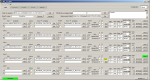
C5 was created following requirements of some customers who were tired to make “by hand” fir filters that combine all functions. With high possibility to make some error and no possibility to have overall look on what is done and no possibility to easy add some new changes.


Let’s clarify some myths about latency that are created by competitors who can not control latency and therefore, are comfortable to keep it high and not defined.
The overall latency of some DSP with analog inputs and outputs is:
converter latency + driver latency + math latency + actual FIR filter latency.
Converter latency is about 1.6 ms for ordinary converters but can be as low as 0.1 ms if we need that.
Other components can be zero and must be zero.
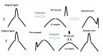
The statement that FIR filter always has latency half of its length in ms, is absolutely incorrect.

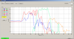
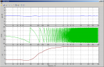
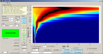
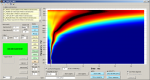
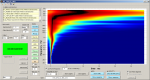
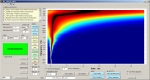
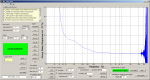
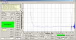
For mentioned example where you see group delay of about 7 ms @ 100 Hz,
2.5 ms @ 300 Hz, 0.7 ms @ 1 kHz and 0 ms from 3 kHz,
But the latency is ZERO (converters excluded) !

We will have 12 (or even 9) ms latency only in case if we use time correction for mentioned group delay.

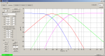
All mentioned is available only if we use LR24 as lowest order crossover, that is doing crossover well. And we can use LR24 (with its relatively wide transition bands) only in case if we have correction in each particular band/way.

I would like to point on possibility to use two mono blocks of DSP for each side of stage/FOH – much less cables …
And that is available by stacking two APL1 PCBs for 4 way system right now.

The stacking of 4 PCBs is creating 4 way stereo DSP.

IMG_1373rp.jpg


Mentioned competitor product can process 2604 coefficients for all FIRs and 650 for one.
It is too much low number to create valuable crossover with corrections.
It incorporates down sampling for lower bands. But there is no warnings about latency required (introduced) by that. But it is huge!
And management is on DOS based system : )))
It is too far for serious competition …
 
Hi Raimonds, It's always great to see a creative innovator coming out with new ideas and products. Thanks for sharing here.

But I have to say, I really don't think that there are alot of myths created by competitors floating around regarding latency.
I think most everybody playing with FIR understands the difference in relatively small DSP processing latencies, and FIR filter length latency.
And I think most folks associate FIR filter length latency with one half it's length, because that's how it works to make linear phase filters. Or at least that's my understanding....pls correct me if I'm wrong.
Anyway, nobody said FIR latency always equals one-half its length in ms; indeed, that's why I put (impulse centering) as a specified condition for the latency figures regarding the number of the taps you describe.

I take it you're you're moving the impulse to the front of the filter. I've been hoping to find time to play with moving off center both directions, to better understand effects......pre/post ringing etc.

I looked at your graphs a little closer and see you went with minimum phase xovers.
I don't yet understand the point in having a boat load of taps just to replicate minimum phase....????
To me, FIR means linear phase. Yes, I get many of the other benefits, but still, just saying....


I completely agree with comments about Monkey Forrest software... just shoot me
But I do think anybody buying the four audio unit fully understands the latency that comes from down sampling (along with the greater low-freq resolution :)

Whatever you build/sell....I'd beg one thing....please do not make it require proprietary software to build the FIR files....
pls let it use files made with programs like FIR Designer, or rePhase.
 
Hi Mark,

Thank you for your thoughts!

I am advocating the use of less ringing (less group delay) minimum phase filters as LR24 for example. They are taking just half of taps as necessary for linear phase filters. Then you can add time correction filter to make that crossover linear phase if you like. It takes just12 ms (and respective number of taps) as in previous example.
You can have on hand two presets – one with zero latency by with some group delay,
another - with linear phase (flat group delay) but with some few ms of latency.

When we are using linear phase filters we are hoping that ringing of one filter will be compensated by ringing of other filter next to it – ringings are out of phase.
It is very utopia hope. As you now, we can use two loudspeakers out of phase but will never get complete compensation of sounds of each other.
Especial, in case when loudspeakers have different construction.
We need to use a correction to make they transfer as identical as possible to go close to that task as possible.
But, if we can use a correction, we do not need to use steep (ringing) filters and the risk of audibility of filter ringing is much less.

All APL solutions (units, plugin) are supporting WAV format FIRs to be uploaded to them.

It is high devastation to use FIRs only for a crossover ...
 
Hi Raimond

I would be interested in a 10ch FIR-box

A couple of things I would like to see in such a box:

- Ethernet-control port with ethercon connector, not USB/RS232 or similar
- Control software with live editing of FIR-filters so that I can change parameters while measuring
- Powercon power input, integrated PSU with automatic 110v/220V switching
- Balanced Analog via XLR, AES/EBU, Dante connectivity

 
Hi Raimonds,

How do you program it to create crossovers, EQ and phase correction?

Obviously you can load a bunch of FIR tap coefficients in to the FIR cores, but what do you use?
 
Ethernet-control?
Digital inputs?
Locking power connector?
What does the 0-15 - pot on the front panel do?
Why is there a power button on the front panel AND the rear panel?

Looks unfinished :) Still, very interesting