60 Degree DIY Mid Hi - AKA PM60

There are several options – yes you can use BMS’s passive crossover on the HF driver and run the system 2 way + Sub. You can then process it on the Lake - its tricky- and flatten the phase response with all pass filters if you want.

The PM60 will work without FIR filters on any quality DSP crossover. The Mid and HF sections MUST be EQ-ed, they are not designed to have a flat response but work as a total system integrated with DSP.

There are quite a few stereo 4 way crossovers which you can use, you just can’t optimise the phase and amplitude response as much as those that have FIR filtering.

One processor that I would like to try is Linea Research ASC-48, I think it would be perfect for this project https://linea-research.co.uk/asc48/
 
Thanks Peter!
Yes I was looking at the ASC48, I like that it has 8 OUTs, which would be perfect for my scope. Have you used it? I'm using DCX464s and I might design a passive crossover later down the line but for now I want full flexibility with tri-amping the PM60s.
Maybe I could use another 2-way DSP crossover between the Lake and DCX464, so the Lake sends out combined Mid-Coax and Hi-Coax signals from 2 of its 6 OUTs, which are then split up in that crossover.

However, wouldn't applying filters with that crossover potentially change the phase again? I guess, independently from this my question is: if I run a FIR-processed signal through another digital unit such as either a crossover or even a soundcard, could this affect the signal, for example its phase? I want to do some fancy routing with an RME fireface post FIR-filtering and of course want to retain whatever I have achieved with applying FIR filtering. This question might reveal that I'm at a quite fresh stage with FIR :)
 
Last edited:
👋Hey peter.I'm a bit new to the DIY sound world and I've been looking to build a set of tops with a mixture of high SPL and excellent fidelity and all fingers point to your designs.:D I've been going through the thread trying to find plans for the PM60/90 but due to all the redesign suggestions and recommendations, I'm not sure which set of plans I should followo_Oo_O. If possible could you send or even link me to the FINAL plans for the PM60 and 90 is possible, thanks🙏
 
[emoji112]Hey peter.I'm a bit new to the DIY sound world and I've been looking to build a set of tops with a mixture of high SPL and excellent fidelity and all fingers point to your designs.:D I've been going through the thread trying to find plans for the PM60/90 but due to all the redesign suggestions and recommendations, I'm not sure which set of plans I should followo_Oo_O. If possible could you send or even link me to the FINAL plans for the PM60 and 90 is possible, thanks[emoji120]

Look ten posts above yours....


Short answer - No ... sorry ... this design requires a crossover point between the 12' drivers and the HF section of between 600 - 700Hz. The ND1460 will not be happy going that low and will not be capable of keeping up with 12' in mids. Thats why the recommend drivers are the BMS4594HE or the B&C DCX464 ... and as a cheeper option 4" diaphargm drivers from B&C, RCF and the 4594 or 4593

B&C DE1090TN - https://bcspeakers.com/en/products/hf-driver/1-4/8/de1090tn

RCF ND950 1.4 https://www.rcf.it/en_US/products/product-detail/nd950-1-4/292823

Peter, thanks for the reply, I found the BMS for a nice price, used one and 16 Ohm. What do you think of connecting 12" in series (8ohm + 8 ohm = 16 Ohm) so bms has the same ohmage? Best wishes ! Paweł
 
Peter, thanks for the reply, I found the BMS for a nice price, used one and 16 Ohm. What do you think of connecting 12" in series (8ohm + 8 ohm = 16 Ohm) so bms has the same ohmage? Best wishes ! Paweł

Yes you can do that ...BUT .... you will need a huge amplifier if you want to take advantage of SPL capabilities of the box. If you use the RCF drivers you would need an amplifier capable of 5000 - 10000 watts per channel into 4 ohms!
 
Hy david thanks for the reply,i saw the zip file but am still worried that it may not be the FINALE version due to everyone questioning its rectangular shape in addition to it lacking some internal curves

It is the final... there are no other drawings unless you make your own. If you actually read the posts... which I guess no one does anymore... you will know the items you question are left up to each builder.


Hy david thanks for the reply,i saw the zip file but am still worried that it may not be the FINALE version due to everyone questioning its rectangular shape in addition to it lacking some internal curves

Just to add to what David said above - the only difference between the version I built and the plan is that I cut the back corner off to make the box look smaller and more professional. The box can not be made trapezoidal without a complete redesign, making the box much bigger, which defeats the original concept of a VERY powerful speaker that can be stick/pole mounted. It also would become VERY difficult to build as a DIY project.

I suspect the best trapezoidal option would be a 10" version .... which would end up looking a bit like this http://mm-acoustics.com/axios-one/#overview
 
Hey everybody, there is an idea.

I could run Topology Optimization to lighten the case. I can calculate where the material does not transfer load. Then you could CNC/mill out the redundant fields, leaving just 0.5cm inner layer for volumetrics/acoustics. It could lighten the case up to about 30% with rather the same stiffness performance. Speak up please if you are interested. I tested it for my table :
cheers
 
Last edited:
Hi Pawel,

The issue with this box and any speaker box for that matter is minimising vibration of the walls as well as the underlying strength of the box. The trick is to have any resonance in the box above the highest operating frequency of the driver it is enclosing (700Hz ) … if you can.

To minimise the weight, the box was designed so that almost every panel had 2 functions; to enclose the 12” drivers and form a wall of the horn or; provide an outside box wall and also be a horn wall. There was no dead space inside the box other than a tiny bit on the top and bottom 2 rear corners ... and the 12" drivers could be installed through the HF horn cut out without the added complexity and weight of separated removable panel to install them.

I did cut off the 2 back vertical corners and I documented the weight saving some where. It also makes the box slightly more rigid. I looked at cutting the top and bottom back corners off (I mentioned above) to save a little more weight but it would limit how stable the box would be when stacked.

While I suspect it would be possible to save more weight by doing what you suggested, I’m not sure how it would impact the resonant issues without adding more bracing and making an already complex build even more difficult … But ... one of the hopes in posting my design was further improvements as everybody shared their ideas and knowledge. :)
 
Last edited:
  • Like
Reactions: Carl Klinkenborg
Hi Pawel,

The issue with this box and any speaker box for that matter is minimising vibration of the walls as well as the underlying strength of the box. The trick is to have any resonance in the box above the highest operating frequency of the driver it is enclosing (700Hz ) … if you can.

To minimise the weight, the box was designed so that almost every panel had 2 functions; to enclose the 12” drivers and form a wall of the horn or; provide an outside box wall and also be a horn wall. There was no dead space inside the box other than a tiny bit on the top and bottom 2 rear corners and the 12" drivers could be installed through the HF horn cut out without the added complexity and weight of separated removable panel to install them.

I did cut off the 2 back vertical corners and I documented the weight saving some where. It also makes the box slightly more rigid. I looked at cutting the top and bottom back corners off (I mentioned above) to save a little more weight but it would limit how stable the box would be when stacked.

While I suspect it would be possible to save more weight by doing what you suggested, I’m not sure how it would impact the resonant issues without adding more bracing and making an already complex build even more difficult to build … But ... one of the hopes in posting my design was further improvements as everybody shared their ideas and knowledge. :)

Hi Peter,

I have gone through all your posts in this topic, I truly admire your ideas and efficiency of this box is astonishing.

It would be more of an experimental or researchable field of development. The solidity of the case impacts resonance for sure. It would be interesting to compare efficiencies with ultra-light Topology Optimized chassis. resonance spreads across solid surfaces in a more or less predictable way depending on material's specification and size which could be simulatable. That would be hard to calculate tho and I am not sure of the cost / effect gauge ;D But still if anybody would be interested I can run the Topology optimisation simulation to see of how could it possibly look like.
 
You should do it and post your results here, it's always interesting to explore new fields. This, if properly executed, could give birth to a whole new generation of loudspeaker design. Using generative design via AI for static engineering in construction is already a thing.
I guess Peter is trying to say, that all panels in the design are 'load-bearing' in an acoustical sense and there is probably little opportunity here. But then again, the situation might change if the box is being altered.
If you want to successfully do this, it would a bit like this, iteratively executing the following steps.; Start with the PM box design and
1) simulate its acoustical response, i.e. standing wave formation/propagation on panels. Using a finite element method or something
2) incrementally subtract and redistribute panel material across the box. Maybe introducing a material with different density. Then step 1) again

This analysis would have to be for every frequency the box is capable to create. Step 2) probably needs some rules as a framework, like 'what shapes/materials break resonances'. The resulting panels might even suggest to be made out of material with density gradients and you would need a specialized fabrication method for these.
I would be curious to see what you come up with :).
 
On the highest resonance/weight saving front, I am making all the main (external) panels on my PM90s using a honeycomb core. 4mm birch ply either side of 16mm Nidaplast - considerably stiffer, lighter, and better damped than 15mm solid but considerably more expensive and time-consuming. I will stick with solid ply for the central enclosure for simplicity of manufacture. It's a nice engineering project though...
The braces (possibly also of sandwich construction) and central enclosure pieces will be rebated right through the inner skin and core to the inside of the outer skin, making a usefully stiffer connection than a shallow rebate in a solid panel. Further, it's overall reduced mass results in lower stored energy; a good thing. It makes the overall dimensions slightly larger, but allows for a nicely radiused or moulded front edge to the enclosure. .
 
Last edited:
On the highest resonance/weight saving front, I am making all the main (external) panels on my PM90s using a honeycomb core. 4mm birch ply either side of 16mm Nidaplast - considerably stiffer, lighter, and better damped than 15mm solid but considerably more expensive and time-consuming. I will stick with solid ply for the central enclosure for simplicity of manufacture. It's a nice engineering project though...
The braces (possibly also of sandwich construction) and central enclosure pieces will be rebated right through the inner skin and core to the inside of the outer skin, making a usefully stiffer connection than a shallow rebate in a solid panel. Further, it's overall reduced mass results in lower stored energy; a good thing. It makes the overall dimensions slightly larger, but allows for a nicely radiused or moulded front edge to the enclosure. .
That sounds promising! Any idea on how you're going to connect the honeycomb core panels 90deg to each other?
 
That sounds promising! Any idea on how you're going to connect the honeycomb core panels 90deg to each other?
Probably by using rather fiddly ninety degree machined plywood joining strips which will be inserted between the skins into rebates where the core has been removed. The outer 4mm skins will be mitred at 45 degrees to keep it crisp and so no joints are visible on the edges. I'm also rather keen to make the horn exits with curved panels rather than joined flat sections. Crazy as it sounds, I've got a hankering after oiled purple-stained burr elm veneer finish; I don't really know where that one came from, but it just won't go away...
I'm not yet quite up to speed on the joint details, but hey; at least I've got all the drivers, Neutrik 8-poles and cables, and enough crossovers and amps!
 
Probably by using rather fiddly ninety degree machined plywood joining strips which will be inserted between the skins into rebates where the core has been removed. The outer 4mm skins will be mitred at 45 degrees to keep it crisp and so no joints are visible on the edges.
'Fiddly' sounds intriguing. You'll be laminating the skins onto the honeycomb with epoxy I assume? I was thinking adding an about 1"wide 16mm thick baltic birch ply strip inside along the sandwich perimeter when you laminate, like a frame. It'll add a bit of weight, but also stability and you could miter them at 45deg. I would be happy to see some pictures of your progress here when you think it's time :-).
 
'Fiddly' sounds intriguing. You'll be laminating the skins onto the honeycomb with epoxy I assume? I was thinking adding an about 1"wide 16mm thick baltic birch ply strip inside along the sandwich perimeter when you laminate, like a frame. It'll add a bit of weight, but also stability and you could miter them at 45deg. I would be happy to see some pictures of your progress here when you think it's time :).
I had thought of that, and it's a considerably simpler solution. I just thought while I was pushing the boat out a little, construction-wise, I would try to avoid simple butt joints of any kind; an 'elegant engineering approach if you will.
I may use a thickened epoxy paste as I most likely will be vacuum bagging the laminated panels. Thickened polyester resin would be adequately strong, considerably cheaper, and less nasty!
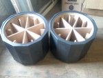
I like a challenge - here are a couple of the sealed 18" upper bass enclosures:
 

Attachments

  • Photo-0062.jpg
    Photo-0062.jpg
    415.9 KB · Views: 91
hi Peter,

I'd like to start building 2 pairs of your PM60.i'll be working off the plans/CAD files MAX posted but before I do I have a question.
what would be the effect of increasing the box's width from 398mm to 419mm.Apart from the increasing weight, I'd like to know if it will have a drastic effect on the box's ability to produce high SPL and clarity.

thank you.

in addition,
Does anyone has a wiring diagram on how the wires of the PM60 are connected to the NEUTRIK STX NL8 and the crossover