FIR filters

Re: FIR filters

This specifically mentions stage monitors, which makes me wonder, do any digital boards come with FIR filters built in?

Regarding Dave's papers. It seems to me that one of the main things he is doing is polarity canceling signal that is reflecting back down the horn. Is this correct?
I have also seen group delay mentioned with the FIR filters. Isn't this a variation on the same theme? And is it dealt with in the same manner?

I remember on the DIY someone (Maybe a Mark?) pointed out a problem with one of the horns at about 3K. Is this something that you fixed with an FIR filter? As in, can the filter fix something that is physically wrong? It seems like this was a bump, not a dip. As pointed out above, a phase problem cannot be fixed, and it seems to me that would be a dip, what about a propagation? Or is this non-linear too?

Mackie and Yamaha had Lake DSP boards that could be fitted to their desks - http://download.yamaha.com/api/asset/file/?language=en&site=ae.yamaha.com&asset_id=53660

This picture below may help explain how time and the lumps and bumps in the frequency response of a linear system are related.

Mechanical systems such as a speaker operating in its piston range can be modelled like an electrical circuit. If for example, the electrical circuit was a 1/3 oct equalizer (I used an XTA GQ600) then this is what happens when you boost and cut one band by 10dB and correct it with an equal and opposite FIR filter so that the response is flat again. I have not show the amplitude response as we all know what it looks like, but note what happens in the time domain.

I set t=0 to 10ms so you could see both sides of the plot.
 

Attachments

  • FIR correction.jpg
    FIR correction.jpg
    341.6 KB · Views: 24
Last edited:
Re: FIR filters

http://circularscience.com/about-drums perhaps TMI about drumhead vibration modes.
circle21.gif


Normal operation of a speaker driver is piston mode where the entire cone moves as one. The difference between piston mode and breakup is pretty significant with lots of extra higher frequency resonances. It is the nature of the physics for round diaphragms that the resonances are not integer harmonics but non-harmonic overtones.

You know more than me about speaks... but that doesn't stop my blather...

JR

These links may be of interest ... http://www.bowers-wilkins.net/Discover/Discover/Technologies/FST.html http://www.bowers-wilkins.net/Discover/Discover/Technologies/Kevlar.html

Once you get beyond the piston range its still a bit of a black art balancing cone materials, profiles and suspension types :)
 
Re: FIR filters

I've vaguely recall reading about the pro's and con's between averaging log-magnitude versus averaging the IR signal directly. Something about the log average being more influenced by level outliers.

Micheal,

Thanks for going over this. I really appreciate the dialog.

I fail to see any advantage in averaging the impulse responses (IRs) directly. Averaging the IRs should be equivalent to averaging the complex frequency response since averaging is addition and a scale factor and the Fourier transform is a linear operator. This would result a dip in the magnitude of the average at a frequency where the individual phases differ, which seems perceptually wrong. A listener at either position would not hear the dip.

I found it useful to pre-smooth (1/24th octave seems to work well) the log magnitude before averaging to get generally less chaotic behavior (and easier to look at graphs) and to address outliers by using the trimmed mean. The trimmed mean is a statistic that can range from the mean to the median in accordance with a parameter, usually called alpha. If the pre-smoothed log magnitude has troublesome outliers you just crank up alpha until they stop influencing the statistic. Going away from the mean does introduce discontinuities in the derivative of the log magnitude, however, so subsequent smoothing is necessary. Another thing I'd like to look at is giving precedence to peaks over dips, which goes with perception. But perhaps this is overkill and it's better just to get more measurements to average.

For the excess-phase all-pass part, too, it makes more sense to me to average the actual characteristic that we're trying to fix, which is phase or group delay. Averaging phase is troublesome, as I think you've observed, which is why I work with group delay. Also, the normalized average group delay is not affected by the time alignment of the individual measurements. The group delay of a later measurement, for example, is just shifted up (more delay) and has an equivalent effect on the normalized average.

Regardless, I need to study IR time alignment more for when you really want to see the average (total) phase. Oversampling (using a sin(x)/x interpolation kernel) and aligning the peaks makes sense but I wonder if it really is physically correct or optimal. What I've been doing is matching the group delay of multiple measurements over a narrow range of frequencies where the phase is well behaved, but that seems kind of ad hoc. One can imagine other, better metrics.

There's nothing like trying to write down some of this stuff to clarify my thinking. Before I could write the above I had to go back and make several tests on the code. I hope that by keeping this open discussion going we all can learn something. Perhaps this should move to DIY audio?

Best,

--Frank
 
Re: FIR filters

Regardless, I need to study IR time alignment more for when you really want to see the average (total) phase. Oversampling (using a sin(x)/x interpolation kernel) and aligning the peaks makes sense but I wonder if it really is physically correct or optimal.

No, this is not correct or optimal. There is still a lot of research going on in this field and the problem is not fully understood as far as I know for a general unknown system. If you decompose the IR into pieces which form a continuous instantaneous frequency, ie you assume it can be represented by an analytic signal, then the delay at the peak of the IR will be the average delay of the of the range of IF which has maximal energy. Obviously, you can form a system where this IS what we colloquially call the delay, but it is not true in general.
 
Last edited:
Re: FIR filters

I'll have to look, I think there is an AES paper/conference proceeding/letter with regards to this, including experimental results. (Heyser maybe?) http://www.aes.org/e-lib/browse.cfm?elib=4526

In radar, they solve this issue by building a dictionary of matched filters for different back-scatters. Then the recorded signal is dechirped, and the matched filters applied for the signal path and back-scatter. The goal being a sinc function with constant phase.
This works with audio too, you can calibrate by making your matched filter.

Obviously the unknown system problem is a bit different, and if you are trying to cross over two sources, with arbitrary filter designs, I'm not sure I would think about it in terms of a global reference, since your goal is constant/equal group delay across the pass band, given ANY global reference. So you should be able to design your FIR filter to land a sinc function with linear phase on the same position when you measure?

Both matched filters should have some constant group delay or excess phase and the difference should be the delay between the two sources. Given you run them over the same bandwidth while you are experimenting.

I just got a couple of the four-audio Hd2 DSPs in the lab so I'll have to play around with it.
 
Last edited:
Re: FIR filters

Raimonds basically has two programs. TDA EQ which basically does what you are talking about. It creates a set of FIR correction tap coefficients. He also has APL Workshop which is used for EQ-ing a system in a room or space.

In simple terms you correct your speaker with TDA EQ. When you set it up in a room you correct the room / speaker with APL Workshop. This correction is based around using the power response not the SPL response.

Our ears do not hear things the same as a measurement microphone .... It's a bit complicated but he argues the power response is a better mechanism than the SPL measurement to base our corrections around. I have tried both and they seem to work :)

Is the sound power response a constant? From annechoic, to outside, to small room?
My understanding is that on Raimonds' TDA, the initial brown line is the power response, and that following (to the right) is the room, and will affect the sound pressure.
 
Re: FIR filters

Is the sound power response a constant? From annechoic, to outside, to small room?
My understanding is that on Raimonds' TDA, the initial brown line is the power response, and that following (to the right) is the room, and will affect the sound pressure.

I purchased TDA & TDA EQ from Raimonds and have plenty of questions on its use and readings but don't want to introduce those here. Would it be appropriate to start a new thread?

Edit- I just noticed someone has started a TDA thread in the DIY Forum so forget this post.
 
Last edited:
Re: FIR filters

Is the sound power response a constant? From annechoic, to outside, to small room?
My understanding is that on Raimonds' TDA, the initial brown line is the power response, and that following (to the right) is the room, and will affect the sound pressure.

Power response is the spatial sum of the acoustical energy being produced by the loudspeaker system for a given input, and is constant for a given loudspeaker. However, a given power response will produce varying frequency responses at the measurement position depending on the acoustical environment the loudspeaker and masurement microphone are placed into.
 
Re: FIR filters

Power response is the spatial sum of the acoustical energy being produced by the loudspeaker system for a given input, and is constant for a given loudspeaker. However, a given power response will produce varying frequency responses at the measurement position depending on the acoustical environment the loudspeaker and masurement microphone are placed into.


Exactly – the power response is as the name suggests - the power emitted by the speaker. It does not account for directivity. If the “power” is emitted in all direction the SPL in front of the speaker will be relatively low, if you concentrate it in a small area (narrow pattern horn) then the SPL will be relatively high.

We generally listen to speakers in a reverberant environment. Raimond’s has used a target power response for correction which typically has 5dB to 6 dB boost in the low frequencies to account for the directivity. This can be modified as necessary. His argument is that this approach better represents what we hear in the field.

A little off topic -- It’s important to understand that what we are hearing (perceive) is different to what a microphone hears.

The part of the ear that contains the hair cells (basilar membrane) is a pseudo-resonant structure. Its behavior can be modeled with an auditory filter bank based on the gammatone function. This information is then sent to the brain which does it best to remove the thing we don’t want hear as part of its processing … it all gets very tricky but what we are perceiving is different to most measurements.

For measuring a speaker in the near field then Systune, Smarrt and TDA EQ all work fine. TDA EQ does give some good information about the time domain issues. Basically in the near field in an anechoic chamber you want flat.


Mechanics of the ear https://www.youtube.com/watch?v=TobHJt1jIHg

Gamma tone https://en.wikipedia.org/wiki/Gammatone_filter

power is the rate of doing work … J /sec = watts
 
Last edited:
Re: FIR filters

Power response is the spatial sum of the acoustical energy being produced by the loudspeaker system for a given input, and is constant for a given loudspeaker. However, a given power response will produce varying frequency responses at the measurement position depending on the acoustical environment the loudspeaker and masurement microphone are placed into.
The poster boy for power response is probably the bose 901... with 89% bouncing off back walls. It makes a difference in how it excites room modes and much more.

On axis response is only one part of the story.

JR
 
Re: FIR filters

On the weekend just gone I used Michael's tool to generate some FIRs for a speaker already installed in a room. Got the response to be +/- 1.5dB from my target curve in most places in coverage of speaker barring within about 2.5m of a wall.
Just a proof of concept for me, but I was stunned at the result...
 
Re: FIR filters

Ah yes, Raimonds's stuff. I've looked at that but never can figure out what on earth he's talking about. I do get that he weights the EQ more toward uniform total power than uniform anechoic SPL at each of a set of points, as most of us do. I'm mainly interested in outdoor speakers and so uniform SPL looks to me like a better starting point. In reverberant settings where total power matters we always can, and often do, "EQ the room" by ear. I will say that his time-frequency-energy plots are the best looking anywhere .... -F

I agree.

The plotting tool looks cool. One challenge with a time analysis tool like this is how to accurately isolate each frequency in a meaningful way. To isolate the level at a fine frequency resolution takes very narrow band filters. The narrower a filter, the longer the filter impulse response. And when looking at the energy in the output of each "filter", where exactly is time t=0? Looking at his "ideal case" time/frequency colour plot - i.e. the plot of a perfect impulse - the plot itself represents the magnitude of the IR's of the "bands" of filters that he uses. And at low frequencies, the IR's are very long. He solves the "where it time t=0" question by essentially using linear-phase band filters - as seen in the time symmetry of the ideal plot with the energy peaking at the same time across frequency.

What he's showing is a similar time/frequency varying behaviour as used in SysTune (TFC window) and it's equivalent in Smaart. His website talks about "bands" of filters but it could be achieved with Fourier transforms (as in Smaart and SysTune). A FFT alone doesn't give the increasingly shorter-in-time effect with increasing frequency that he shows but FFT data can be manipulated to achieve this, or different transform lengths used at different frequencies. (Wavelet transforms inherently have this time/frequency varying behaviour and used to be touted as the answer to every problem in signal processing. I haven't seen them for sometime!)

I'm also confused by his descriptions of his amplitude and phase solutions and it seems some information is lost with English not being his first language.
 
Last edited:
Re: FIR filters

The narrower a filter, the longer the filter impulse response.

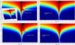
Yes, we're up against the uncertainty relationship. We can have time resolution or frequency resolution but not arbitrarily much of both. I believe the Wigner distribution, which is the 2-d Fourier transform of the ambiguity function familiar to radar folks, does the best is this regard, but the plots are riddled with artifacts that make them hard to interpret for audio. I can say what I'm using, which is based on a paper by Dave Gunness but computed a little differently. I'm guessing this is equivalent to what most folks are doing now, and probably Raimonds, too.

--Start with the windowed impulse response

--Take the DFT to get the complex frequency response.

--Window the FR with constant-octave-spaced, constant-octave-bandwidth Gaussian windows to get the frequency bands. (The Gaussian is of infinite extent but it gets so small so fast that it's OK to truncate it at the size of the transform.)

--Take the discrete Hilbert transform of each windowed band to get the time-domain analytic signals.

--Take the log magnitude of each and plot with pretty colors.

So what you have (waving hands in the time direction) is the log magnitude of the analytic signal corresponding to the impulse response of the system passed through a set of Gaussian band-pass filters.

I've tried to plot these both with a normal time axis and with the time axis in phase units (cycles, degrees, etc.) thereby stretching the high frequencies in the time direction. I think I like the normal time axis better. Another thing that I like a lot is to plot the ridge in a different color. The shape of the ridge, viewed looking normal to the t-f plane, strongly resembles the group delay.

For most filter/alignment work I think these representations are somewhat superfluous. Good old mag and phase plots pretty much tell the whole story. I have found them useful as a somewhat independent check on what filters do.

Agree about wavelets. They were all the rage right after I graduated in the mid '80s (I missed out) but I don't hear much now. But I'm kinda out of touch.

--Frank
 
Re: FIR filters

--Start with the windowed impulse response

--Take the DFT to get the complex frequency response.

--Window the FR with constant-octave-spaced, constant-octave-bandwidth Gaussian windows to get the frequency bands. (The Gaussian is of infinite extent but it gets so small so fast that it's OK to truncate it at the size of the transform.)

--Take the discrete Hilbert transform of each windowed band to get the time-domain analytic signals.

--Take the log magnitude of each and plot with pretty colors.

So what you have (waving hands in the time direction) is the log magnitude of the analytic signal corresponding to the impulse response of the system passed through a set of Gaussian band-pass filters.

Thanks. I suspect the initial window might be redundant, since the Gaussian window in the frequency domain is doing all the work and its time tails are low in amplitude near where the transform window would be rolling down. (I just tried a ~1/6th octave Gaussian freq filter at about 10 kHz in Matlab for a 32768 length transform and the time tails of the IFFT are below -100 dB.)

I think the Hilbert transform here is converting the linear-phase Gaussian IR into a minimum phase for each band. And in a colour plot of a single impulse, this should give a single sided plot (i.e. not symmetric as in Raimonds). Is that what you see? I may be wrong. I think just a IDFT/IFFT of each band (followed by log magnitude and pretty colours) will give a symmetric plot like Raimonds.

Cheers,
Michael
 
Last edited: