FIR filters

Re: FIR filters

The key here is recognizing what can and cannot be corrected with DSP, and what can and cannot be corrected purely in the mechanical domain.

I've seen so many folks say this.
Will those of you 'in the know' regarding what can and can't be corrected, please share said info. ?

I get some things that can't...non linear items like THD and resonances. Other can'ts?

And what are the specific cans?
 
Re: FIR filters

Not a simple answer, I expect...

FWIW some distortion can be anticipated and corrected by pre-distorting the signal, before hand, but requires specific knowledge of levels and nature of the non-linearity.

JR
 
Re: FIR filters

I've seen so many folks say this.
Will those of you 'in the know' regarding what can and can't be corrected, please share said info. ?

I get some things that can't...non linear items like THD and resonances. Other can'ts?

And what are the specific cans?

Mark,
I would check out some of the papers Bennett posted in post 17. Dave details quite well his different applications and processes. Just a note that much of what he is doing may be protected under patents, so I wouldn't except other companies to be able to implement his technology without specific agreements.


Sent from my iPhone
 
Re: FIR filters

Mark,
I would check out some of the papers Bennett posted in post 17. Dave details quite well his different applications and processes. Just a note that much of what he is doing may be protected under patents, so I wouldn't except other companies to be able to implement his technology without specific agreements.


Sent from my iPhone

Thanks David, ...and thanks Bennet. Yep, good informative reading for sure...I already see I misunderstood what people were saying about horn resonances..:?~:-?~:???:
 
Re: FIR filters

I've seen so many folks say this.
Will those of you 'in the know' regarding what can and can't be corrected, please share said info. ?

I get some things that can't...non linear items like THD and resonances. Other can'ts?

And what are the specific cans?

Hi Mark,

You should be able to fix resonant issues, but not things caused by cone / diaphragm break up or phase cancelation (excluding time alignment issues). That's why the DIY that you are building has the low, mid and high drivers all operating in their piston range ... It can be fixed.

i think you could (but not with FIR filters) correct for the non linear compression of the air in a compression driver which will cause some 2nd harmonic distortion ..... But 2nd harmonic distortion tends to be masked some what and is not as noticeable as higher order distortion or sub harmonics.
 
Re: FIR filters

Hi Mark,

You should be able to fix resonant issues, but not things caused by cone / diaphragm break up or phase cancelation (excluding time alignment issues). That's why the DIY that you are building has the low, mid and high drivers all operating in their piston range ... It can be fixed.

i think you could (but not with FIR filters) correct for the non linear compression of the air in a compression driver which will cause some 2nd harmonic distortion ..... But 2nd harmonic distortion tends to be masked some what and is not as noticeable as higher order distortion or sub harmonics.

Hi Peter, thanks! Is it safe to assume rising THD, or some particular level of THD, is the onset of cone/diaphragm breakup?
 
Re: FIR filters

Hi Peter, thanks! Is it safe to assume rising THD, or some particular level of THD, is the onset of cone/diaphragm breakup?

I wouldn't ASSume that. I am not the speaker expert here but speaker break up modes are not unlike drum head vibration modes (I know a little about that). So a different kind of resonance more than a non-linearity.

JR
 
Re: FIR filters

I wouldn't ASSume that. I am not the speaker expert here but speaker break up modes are not unlike drum head vibration modes (I know a little about that). So a different kind of resonance more than a non-linearity.

JR

Ah ... drum head behaviour, it's a worry but I still remember this from Uni mathematics :-/
.... It can be described by the solution of a second order partial differential equation with the appropriate boundary conditions - wave equation. There are some cool animations on the web.

To me the easiest way to see where cone or diaphragm break is occuring is where the smooth-ish frequency response becomes at bit ragged. For a cone driver the directivity also narrows as the center of the speaker decouples (sort of) from the outer parts of the cone. With a compression driver the wave front shape is usually compromised.

There are lots of things that contribe to distortion - the linear behaviour of the motor, the suspension, cone breakup, resonances etc.

Im not a speaker designer either .... So if anyone can correct me or add some information please do so.
 
Last edited:
Re: FIR filters

As I understand it, the real tricks/challenges are in getting accurate, useful measurements at the right drive levels, and in the time alignment and averaging. One could also model the IR of the early part of the horn. From what I've read and heard, Dave has developed methods for doing both to "fix" the time domain response.

I've been working on just this problem. Synthesizing arbitrary FIR filters given a prototype response is comparatively easy, although there, too, are some tricks that they didn't teach us in school, as we discussed in Montreal.

At this point my approach to obtaining a prototype response is to generate a minimum phase FIR filter from the smoothed, statistically combined log-magnitude of multiple measurements. This takes out pretty much all of the fine detail ("grass") in the magnitude and phase response and, since the filter depends on magnitude alone, the time alignment of the individual measurements is irrelevant. Furthermore, the relative gains of the individual measurements also are irrelevant as the log-magnitudes, rather than the magnitudes, are being averaged.

I combine (convolve) this filter with an FIR all-pass to take out the excess phase. The beauty is that excess phase anomalies tend to vary slowly with frequency and angle (except in the top octave of certain compression drivers, it seems) so the time alignment of the measurements is not that critical. Simply aligning the peaks of the impulse responses (to the nearest sample) appears to be sufficient. The absolute time alignment is also irrelevant, as I normalize the combined group delay so that the filter is "doing as little as possible". We don't care about bulk delay of the entire signal, within reason. Normalizing the derivative of the phase (group delay) is analogous to normalizing the the log-magnitude in the minimum phase filter.

In due course I'll post some signal flow charts (block diagrams) and typical graphs here. It'll take me a bit to get it all together. I'm likely reinventing the wheel (and maybe getting it wrong) but I'm having fun.

Best,

--Frank
 
Re: FIR filters

I've been working on just this problem. Synthesizing arbitrary FIR filters given a prototype response is comparatively easy, although there, too, are some tricks that they didn't teach us in school, as we discussed in Montreal.

At this point my approach to obtaining a prototype response is to generate a minimum phase FIR filter from the smoothed, statistically combined log-magnitude of multiple measurements. This takes out pretty much all of the fine detail ("grass") in the magnitude and phase response and, since the filter depends on magnitude alone, the time alignment of the individual measurements is irrelevant. Furthermore, the relative gains of the individual measurements also are irrelevant as the log-magnitudes, rather than the magnitudes, are being averaged.

I combine (convolve) this filter with an FIR all-pass to take out the excess phase. The beauty is that excess phase anomalies tend to vary slowly with frequency and angle (except in the top octave of certain compression drivers, it seems) so the time alignment of the measurements is not that critical. Simply aligning the peaks of the impulse responses (to the nearest sample) appears to be sufficient. The absolute time alignment is also irrelevant, as I normalize the combined group delay so that the filter is "doing as little as possible". We don't care about bulk delay of the entire signal, within reason. Normalizing the derivative of the phase (group delay) is analogous to normalizing the the log-magnitude in the minimum phase filter.

In due course I'll post some signal flow charts (block diagrams) and typical graphs here. It'll take me a bit to get it all together. I'm likely reinventing the wheel (and maybe getting it wrong) but I'm having fun.

Best,

--Frank
FWIW this is what I used on the DIY http://aplaudio.com/conc2/products/tda-eq/ the phase correction is not enabled so I used some all-pass filters that I applied manually with the help of Systune :)
 
Re: FIR filters

Ah ... drum head behaviour, it's a worry but I still remember this from Uni mathematics :-/
.... It can be described by the solution of a second order partial differential equation with the appropriate boundary conditions - wave equation. There are some cool animations on the web.
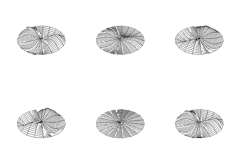
http://circularscience.com/about-drums perhaps TMI about drumhead vibration modes.
circle21.gif

To me the easiest way to see where cone or diaphragm break is occuring is where the smooth-ish frequency response becomes at bit ragged. For a cone driver the directivity also narrows as the center of the speaker decouples (sort of) from the outer parts of the cone. With a compression driver the wave front shape is usually compromised.
Normal operation of a speaker driver is piston mode where the entire cone moves as one. The difference between piston mode and breakup is pretty significant with lots of extra higher frequency resonances. It is the nature of the physics for round diaphragms that the resonances are not integer harmonics but non-harmonic overtones.
There are lots of things that contribe to distortion - the linear behaviour of the motor, the suspension, cone breakup, resonances etc.

Im not a speaker designer either .... So if anyone can correct me or add some information please do so.
You know more than me about speaks... but that doesn't stop my blather...

JR
 
Re: FIR filters

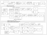
Here is a signal flow of my FIR filter coefficient cooking process at an intermediate level of detail. There are also some pretty pictures taken at a few places along the way to give some flavor. Should anyone be interested in going into more detail we should prob do that off-line. --Frank

MultiBrutalBlock.jpg
TMSM.jpg
TMEGD.jpg
FilteMagFit.jpg
CoeffOut.jpg
 
Re: FIR filters

FWIW this is what I used on the DIY http://aplaudio.com/conc2/products/tda-eq/ the phase correction is not enabled so I used some all-pass filters that I applied manually with the help of Systune :)

Ah yes, Raimonds's stuff. I've looked at that but never can figure out what on earth he's talking about. I do get that he weights the EQ more toward uniform total power than uniform anechoic SPL at each of a set of points, as most of us do. I'm mainly interested in outdoor speakers and so uniform SPL looks to me like a better starting point. In reverberant settings where total power matters we always can, and often do, "EQ the room" by ear. I will say that his time-frequency-energy plots are the best looking anywhere and I'm thinking of plagiarizing his color pallet. -F
 
Re: FIR filters

FWIW this is what I used on the DIY http://aplaudio.com/conc2/products/tda-eq/ the phase correction is not enabled so I used some all-pass filters that I applied manually with the help of Systune :)

This specifically mentions stage monitors, which makes me wonder, do any digital boards come with FIR filters built in?

Regarding Dave's papers. It seems to me that one of the main things he is doing is polarity canceling signal that is reflecting back down the horn. Is this correct?
I have also seen group delay mentioned with the FIR filters. Isn't this a variation on the same theme? And is it dealt with in the same manner?

I remember on the DIY someone (Maybe a Mark?) pointed out a problem with one of the horns at about 3K. Is this something that you fixed with an FIR filter? As in, can the filter fix something that is physically wrong? It seems like this was a bump, not a dip. As pointed out above, a phase problem cannot be fixed, and it seems to me that would be a dip, what about a propagation? Or is this non-linear too?
 
Re: FIR filters

Here is a signal flow of my FIR filter coefficient cooking process at an intermediate level of detail. There are also some pretty pictures taken at a few places along the way to give some flavor. Should anyone be interested in going into more detail we should prob do that off-line. --Frank

Frank,

Have you experimented much with truncating your filter so that the processing delay is less?
 
Re: FIR filters

Frank, Have you experimented much with truncating your filter so that the processing delay is less?

Bennett,

Sure. As a practical matter I'm limited to 384 samples at fs = 48kHz because of the DSP I'm using (Powersoft) so a total filter length of 8 ms. Since after optimization the peak of the filter falls somewhere near the center of the window the processing delays are running around 3 to 5 ms, which for an outdoor main speaker I consider just fine. Monitors might be a different story. I experiment with longer filters to see what they do on paper but I can't actually listen to them.

One observation for the general reader is that the minimum phase part of the FIR filter has essentially zero processing delay as it is one-sided or "causal" as SP types say. It is not necessary to use excess group delay compensation (for a well behaved speaker) or uniform group delay crossover filters (we got along for years without them) so the processing delay can be kept very short for, say, a monitor.

Right now I'm looking at adding compensation for the phase shift of the natural high-pass of the speaker (mid-high only) without compensating the magnitude. There are really a lot of different things you can do with these tools. The hard part is knowing what are real problems that need to be solved. I'm taking suggestions.

Best,

--Frank
 
Re: FIR filters

Ok - I opened up a can of worms I wasn't prepared for. Like Tim implied "how's your math?" ............ not good enough.

Very interesting stuff, but I have no desire (at this point) to understand the math of FIR. I was really looking for a laymens explanation of FIR. Here is what I think it is, what it does, and why it is better than standard EQ and Crossover filters.

1. FIR filters can apply EQ and Crossover filter functions like the traditional filters (LR, BW, Parametric, etc.) but in a different way using complex mathmatical algorithms.

2. PROS of FIR:
a: no time based issues like traditional filters: phase and cancelation
b: more headroom/gain in dB due to the lack of phase cancelations
c: better horizontal coverage due to lack of phase issues

3. CONS of FIR:
a. requires more DSP
b. time and cost to develop and test FIR dsp settings

Please correct any of my assumptions.

Thanks again!
 
Re: FIR filters

Ah yes, Raimonds's stuff. I've looked at that but never can figure out what on earth he's talking about. I do get that he weights the EQ more toward uniform total power than uniform anechoic SPL at each of a set of points, as most of us do. I'm mainly interested in outdoor speakers and so uniform SPL looks to me like a better starting point. In reverberant settings where total power matters we always can, and often do, "EQ the room" by ear. I will say that his time-frequency-energy plots are the best looking anywhere and I'm thinking of plagiarizing his color pallet. -F

Raimonds basically has two programs. TDA EQ which basically does what you are talking about. It creates a set of FIR correction tap coefficients. He also has APL Workshop which is used for EQ-ing a system in a room or space.

In simple terms you correct your speaker with TDA EQ. When you set it up in a room you correct the room / speaker with APL Workshop. This correction is based around using the power response not the SPL response.

Our ears do not hear things the same as a measurement microphone .... It's a bit complicated but he argues the power response is a better mechanism than the SPL measurement to base our corrections around. I have tried both and they seem to work :)
 
Last edited:
Re: FIR filters

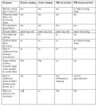
In an attempt to answer Sean's original question I've put together a table that compares various filter implementations. It is neither rigorous nor complete. Sorry it's an image but that's the only way I know to get a table in the forum. -F

FilterProperties.jpg
 
Re: FIR filters

Here is a signal flow of my FIR filter coefficient cooking process at an intermediate level of detail. There are also some pretty pictures taken at a few places along the way to give some flavor. Should anyone be interested in going into more detail we should prob do that off-line. --Frank

View attachment 13993
View attachment 13992
View attachment 13994
View attachment 13995
View attachment 13996

Thanks very much Frank. My apologies in advance for taking some time to think over this.

To your earlier post. You mentioned averaging the log-magnitude of multiple measurements, without respect to time alignment, to make a good magnitude response, and then make a minimum phase FIR. That makes sense. I've vaguely recall reading about the pro's and con's between averaging log-magnitude versus averaging the IR signal directly. Something about the log average being more influenced by level outliers. Without more thought, I don't have an opinion here but I thought it's worth mentioning.

The Auto Mag tab on my app creates a minimum-phase FIR. (I might add a linear phase option.) Your step to combine this filter minimum-phase with a FIR all-pass sounds very similar to the manual Phase Adjust on my app. I apply the manual Phase Adjust first, so the Auto Mag and Auto Phase processes don't have to fight with the excessive phase. I guess you're doing this too.

A few weeks ago I discovered that the complex averaging in the frequency smoothing in the Auto Mag process was loosing energy when there was excessive phase rotation in the response. To prevent this, I added the option for magnitude-only frequency smoothing. This helps a lot for some messy measurements, or for filters where the manual Phase Adjust page has high phase rotation added. Why one would extra phase slope, I don't know, since the intent is to make phase smoother!

In the context of high frequency corrections, such as fixing horn resonances, I suspect that direct IR averaging is necessary and possibly with oversampling to get the most accurate time alignment possible. Steve Anderson and I were just yesterday discussing this, and I can easily write a tool that, for example, reads all the IR's in a directory, does oversampling, time (and maybe level) alignment, and spits out the average response. If the files are annotated with direction, it could apply some directional weighting, or other heuristics. I could maybe add multiple-measurement averaging as an import option in the FIR tool.
 
Last edited: