Line Level Isolation Transformers

Geoff Doane

Sophomore
Nov 19, 2011
116
0
16
Halifax, NS
I see most of the threads here involve speaker design, or other woodworking related topics. My interests generally run in the direction of metal bashing and soldering rather than sawing (sawdust is too messy :lol:), so here's my contribution for what I hope is a useful isolation transformer design. Tom Manchester started a similar thread a while back, but I'm not sure if the project ever really got off the ground. Hopefully this will germinate some ideas for other members of the forum.

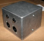
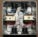
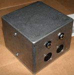
This project started with a clean-up around the shop, and a box of die cast Hammond cases that were in danger of being thrown out because no one remembered what they had been bought for. Being the pack rat that I am, I offered to give them a new home. I had previously salvaged some 1:1 transformers from an old MCI JH-636 studio console that had been parted out. I didn't have any specs on them, but they were fairly sizable, which is generally a good sign for transformers, and coming from an MCI, they were likely decent performers. The boxes were a little odd, in that they were almost cubic in their dimensions, but I figured I could fit two transformers and the associated connectors in each one, for a 2-channel isolation box.

One of the design goals was to make a box that could adapt between XLR, 1/4", balanced and unbalanced, and do it in either direction. I used Neutrik TRS jacks in parallel with the male and female XLRs, on all three contacts (T,R,S to 2,3,1). The transformer windings are connected to pins 2 and 3. Ground (pin 1) is not connected between input and output. Some people might put a switch in there, but I'm rather reluctant to do that because toggle switches are easily broken, can be set to the "wrong" position, and since this is an isolation box, lifted is generally what you want anyway. I had thought about putting a small value capacitor (0.01 µF) to provide an RF path between the grounds on either side of the box, and I may still do that.

The leads on the transformers had originally been connected to Molex connectors (an unfortunate trademark of MCI products), and were a bit on the short side, but with the mounting arrangement they just reached the XLR solder cups. 24 ga. stranded hookup wire was used to jump to the TRS jacks. The audio performance turns out to be pretty good. I did some quick checks with an Audio Precision Portable One (I'm not yet in the Smaart camp), and at +20 dBu, the distortion is good, even down in the 10-20 Hz range. Feeding it with a low source impedance, and into a high load impedance the frequency response was also virtually flat from 10-30 kHz. Some other transformers I've used for this in the past needed a damping resistance on the load (typically 5 kΩ) to avoid a bump around 10 kHz, but this was fine without it. I'll do a more comprehensive test if anyone is interested.

One thing I didn't test (and I'm not sure how you would spec such a thing) is the box's susceptibility to stray magnetic fields. I've had trouble with cheap wall warts in the past, making otherwise good DIs hum like crazy. These transformers don't seem to have any magnetic shielding, and the die cast aluminum case is impervious to fields, so that is a potential problem.

One other design feature I haven't yet decided on is how to label the thing. The cheap and dirty method would be P-touch labeling, which has been fairly durable for other items. Or I could spend about $40 per box and get them engraved, but it's a little hard to justify that when I've only spent about $8 (the cost of the connectors) plus sweat equity on each of them so far. Any experienced tech should recognize which jack is the input, although that may not be all that critical anyway with a 1:1 transformer. Any suggestions?

GTD
ISO-1.jpgISO-2.jpgISO-3.jpg
 
Re: Line Level Isolation Transformers

Looks good Geoff. I did end up building one a while back, it looks almost identical to the one you made, only without the 1/4" connectors. I haven't had much need to use mine fortunately, but the one time I used it, it worked well. My only project cost was a plastic project box which I lined with foil tape, so about $4. The rest of the parts were salvaged.
 
Re: Line Level Isolation Transformers

You may want to label which input and output connectors are paralleled to each other. Other than that, I think "This Is Not A Step" should go on top. :)
 
Re: Line Level Isolation Transformers

My only project cost was a plastic project box which I lined with foil tape

The question of shielding is one I have to admit to ignoring for this project. It's built in an aluminum box, which should provide some RF shielding, but not for magnetic fields. The box is also not connected to any of the other grounds, the same as any other snake box I've ever seen, to try and prevent unintentional ground loops. Maybe I should RF ground the pin 1s to each other and the case with small capacitors?

Jordan: since it's a diecast box, it would probably work OK as a step, or even a wheel chock in a pinch. :twisted:

GTD
 
Update: Line Level Isolation Transformers

I made a decision on what to do with the grounds in the boxes. I've taken the audio grounds (pin 1 and S) to the chassis through a 0.01 µF capacitor. The value was chosen because it's virtually an open circuit at hum frequencies (60, 120 Hz), but is quite a low impedance in the RF range (1 MHz and up). And I had a bag of them lying around after another similar project.

GTD

ISO-4.jpg
 
Re: Line Level Isolation Transformers

Does nobody care about AES-48?

I have to admit that I didn't know exactly what AES48 was, but after I Googled it, I see it's the official name for the solution to the "Pin 1 problem".

I'm not sure that it applies in this case, since the box is passive (AES48 seems to be for active devices). I suppose I could connect pin 1 directly to the chassis (the essence of AES48, I think), but that might inadvertently cause a ground loop if the chassis was touching another piece of equipment. It also could cause a problem if the transformer was used in reverse (think using it in line with snake "sends" rather than "returns", even if it is a return feed, so the gender is reversed).

Commercially available snakes almost always just float the stage box. The only exception I can think of is the Canare line, which has a separate drain wire for the boxes, although I'm not sure what you're supposed to do with that drain wire at the fan end of the snake. Of course in an installation, any raceways (conduits, junction boxes) are supposed to be bonded to ground by electrical code.

The transformers would typically be used when a pin 1 problem does exist, and only after a hum has been discovered. I see them being useful when attempting to interface my system with a house rig of questionable integrity.

Would you have an alternate suggestion? I'm interested in hearing all the pros and cons I can on this subject.

GTD
 
Re: Line Level Isolation Transformers

I would just leave the grounds "lifted", or maybe add a switch that allows you to connect them. I see no reason they should be bonded to the case in any way.

I would use the same technique as many direct boxes Ground through a switch but put a cap across the switch for RF grounding.
http://www.jensen-transformers.com/datashts/dbe.pdf
I checked with Jensen before coming out with my DI box and they say the resistor is not needed, just the cap.

BTW I think it is important to NOT ground the shell of the XLR jacks. Many cords have Pin 1 incorrectly connected to the shell, If you use one of these, you defeat your ground lift and it can be confusing when you are trying to get rid of hum and are in a hurry.

Frank
 
Re: Line Level Isolation Transformers

BTW I think it is important to NOT ground the shell of the XLR jacks. Many cords have Pin 1 incorrectly connected to the shell, If you use one of these, you defeat your ground lift and it can be confusing when you are trying to get rid of hum and are in a hurry.

Frank

That's one of the advantages of using the plastic chassis connectors. Even if an XLR has the shell connected, it won't go anywhere on the box, unless it touches something else inadvertently.

The current scheme is essentially ground lifted with an RF bypass (like Jensen's recommendation) but there is no option to connect the ground. As I said in the first post, I'd like to avoid switches if possible. I made some similar boxes a few years ago that had two input XLRs for each channel. One had the ground connected and the other was lifted with an RF bypass. It takes more real estate that way, but the cost of the plastic XLR is about the same as a toggle switch.

GTD
 
Re: Line Level Isolation Transformers

I agree with the notion of losing the "ground lift" switch and leaving the grounds permanently disconnected. As you point out, that's why you're using an iso transformer in the first place.

One thing that occurred to me (in the honored engineering tradition of solving problems you don't have) is to use a transient voltage suppressor between the grounds of the two sides, in addition to a small RF bypass cap. This would help protect the transformer, cap, and, perhaps, personnel from voltage spikes.

This is a timely thread as I, too, am about to build some isolation boxes around some junk box, er, I mean vintage, transformers. (UTC A-22s in my case.)

I'll probably bond the output side ground to the case for electrostatic shielding on mine, but understand the case for not doing so.

--Frank
 
Re: Line Level Isolation Transformers

One thing that occurred to me (in the honored engineering tradition of solving problems you don't have) is to use a transient voltage suppressor between the grounds of the two sides, in addition to a small RF bypass cap. This would help protect the transformer, cap, and, perhaps, personnel from voltage spikes.

--Frank

Most TVSS devices are shunt mode, and require a low impedance drain path. If such a device is placed between the 2 grounds in the system, where would it drain to? Chassis?
 
Re: Line Level Isolation Transformers

Most TVSS devices are shunt mode, and require a low impedance drain path. If such a device is placed between the 2 grounds in the system, where would it drain to? Chassis?

TVSs are indeed shunt mode. They have a high impedance until some voltage threshold is exceeded, at which point they break down and present a low impedance for a short while. I was thinking of a two terminal device connected between the grounds that would simply protect the transformer from breakdown between the windings. And this is assuming that clamping the grounds together will keep the signal lines together, so far as spikes are concerned. Maybe one should forget about the grounds and put TVSs between the signal lines on both sides. And if you've got 500V spikes coming down your audio cables, there may be bigger problems. Like I said, I'm probably trying to solve a problem that doesn't exist. There's just such a strong temptation to want to put SOMETHING between the grounds :razz: Stuff to think about...

--Frank
 
Re: Line Level Isolation Transformers

I would just leave the grounds "lifted", or maybe add a switch that allows you to connect them. I see no reason they should be bonded to the case in any way.

if this is a passive box, made of metal, why shouldn't it be connected to pin 1?
the purpose of the box (if the builder spent the extra bucks on metal) is to shield the internals, so it should by definition be grounded.
If the shield of the XLR connected to it is grounded, I can't picture any scenario where it would be harmful to have this box connected to the shield of the incoming XLR (at least) and why not continue the ground through?
the unbalanced output could be lifted by a capacitor, but leaving the entire chassis of the device (active or not) floating doesn't help anything..

(I could be wrong.. although I am signed up for Bill Whitlock's course at Infocomm and after that I hope to be right 100% of the time) :)

Jason
 
Re: Line Level Isolation Transformers

In an ideal world there wouldn't be much need for a line level isolation transformer, so the implication is this will be applied to mitigate some ground problem.

Modern properly designed gear should handle pin 1 currents without corrupting the audio signal integrity, but there is enough legacy gear still in use to worry about. IMO the chassis should be hard tied to pin 1 on either the input or output. A ground lift switch can open the connection between Pin 1 input and Pin 1 output. I also like the small cap always in circuit to provide a low Z RF shield ground path, and even a high value resistor to drain off static charge, if present. If no charge is present the high value resistor will not conduct enough current to be a problem.

JR

edit/ back in the early '80s I experimented with using back to back diodes between signal ground and chassis ground, to ignore low voltage ground potential differences, while still providing a low impedance path for larger voltages/currents (I used power rectifiers that were quite robust.).

For a "fixer" Isolation transformer, it might be nice to add a LED and resistor across the switch open position that could light up to indicate if a large voltage potential exists across the grounds, something that would be useful to know for human safety. /edit
 
Last edited:
Re: Line Level Isolation Transformers

Sorry to necro-post and all that, but you did link to this thread from that other thread and I finally just read this thread.

How is the cross talk between the two channels of this box? Especially at high levels?

When I initially looked at your photos I was quite impressed with how everything went together so nicely, but then it dawned on me that the transformers are oriented with the magnetics in the same plane. I would think that it may be possible for one channel, if exposed to high signal levels, to have its magnetic field picked up by the other transformer, especially if there is little to no signal on the other transformer and thus, very little magnetic field of its own.

If this happens, I would expect that by rotating the mounting base of one transformer by 90 degrees, you could stop this from happening completely.
 
Re: Line Level Isolation Transformers

if this is a passive box, made of metal, why shouldn't it be connected to pin 1?
the purpose of the box (if the builder spent the extra bucks on metal) is to shield the internals, so it should by definition be grounded.
If the shield of the XLR connected to it is grounded, I can't picture any scenario where it would be harmful to have this box connected to the shield of the incoming XLR (at least) and why not continue the ground through?
the unbalanced output could be lifted by a capacitor, but leaving the entire chassis of the device (active or not) floating doesn't help anything..

(I could be wrong.. although I am signed up for Bill Whitlock's course at Infocomm and after that I hope to be right 100% of the time) :)

Jason
The reason being that this is a TWO channel box. So there is a possibility of two different paths-for whatever reason.

It is was a single channel box-then that is a different issue.
 
Re: Line Level Isolation Transformers

Seems building a MuMetal box around each transformer would kill both inter-transformer interaction as well as pickup of stray EMF fields.
 
Re: Line Level Isolation Transformers

Sorry to necro-post and all that, but you did link to this thread from that other thread and I finally just read this thread.

How is the cross talk between the two channels of this box? Especially at high levels?

When I initially looked at your photos I was quite impressed with how everything went together so nicely, but then it dawned on me that the transformers are oriented with the magnetics in the same plane. I would think that it may be possible for one channel, if exposed to high signal levels, to have its magnetic field picked up by the other transformer, especially if there is little to no signal on the other transformer and thus, very little magnetic field of its own.

If this happens, I would expect that by rotating the mounting base of one transformer by 90 degrees, you could stop this from happening completely.

That's a good point Josh, and to be honest, I hadn't really thought about it. I have had trouble with stray fields from wall warts getting into even mu metal shielded transformers, so there certainly is a chance of crosstalk. Unfortunately, the leads are so short, I don't think I could turn one transformer 90º. Maybe I could turn both of them 45º in opposite directions. I'll measure it next week when I get a chance with the AP test set. MCI used similar PC mounted pairs of transformers in another console, and installed a fairly thick shield between the two cores, so maybe there is the possibility of interference from one to the other.

GTD