Well, THAT's Not Gonna Fucking Work!

Re: Well, THAT's Not Gonna Fucking Work!

Commonly a forth order filter will be used for dc blocking. I haven't seen a measurement below 20 Hz yet. See attached jpeg. Sorry I just plotted the digital IIR filter not an actual active one.
Thanks for that, I went looking for that exact picture last night but couldn’t find exactly what I wanted.

Peter
 
Re: Well, THAT's Not Gonna Fucking Work!

I just want to say one more thing which I think is important. I have been thinking about this thread and all of the responses to it.
What made me reel at first reading this post was the 30deg laggy comment. This doesn't make any sense because phase vs. frequency doesn't mean laggy at all. In a non-physical sense, phase can be equated to instantaneous frequency, or "group" delay but nothing more. Phase does not add up as you move along the frequency axis. If you take the strict nonphysical definition of phase in relation to instantaneous frequency, then group delay is the negative derivative of phase. Every audio naive should know this by now. There are no sums involved in a derivative.
The second thing that made me confused was the fact I do not know where SMAART decided to set t0 after it conducted its measurement. I am assuming SMAART computed an impulse response from the measurement, then chose an appropriate t0 position, then computed the FFT to resolve the magnitude and phase curves displayed. Numerous other methods could have been used but none of them would involve an exact t0 for the phase measurement. They all depend on numerical devolution methods in some way or ‘transform’. I’m sorry I don’t really know much about these stochastic methods of measuring frequency response. I do assume that the same principles apply to them as deterministic stimuli. These methods work awesome for band limited acoustic signals when measuring loudspeakers but start to fail when the signal appears to fill the entire Nyquist bandwidth.
When measuring a DSP I would have pushed a frequency through the DSP and measured the phase relative at that one frequency simultaneously on the multiple channels. A stepped sine measurement if you will; Neither a Farina style logarithmic "swept sine" or MLS type measurement could be as exact as stepping with known and simultaneous signals over multiple wavelengths. This is especially true at the very low and very high frequencies. I have measured many pieces of equipment where the HF noise will correlate very well with the stimuli in the HF and cause an erroneous phase curve well before they will affect the magnitude response.
None the less, I am assuming SMAART turned out to be quite accurate based on the other posts which seem to support Bennett’s original measurement. So, sorry everyone, that I attacked the original post. I made some guesses about why this DSP might look like this. I just hope I get a chance to measure one myself at some point.
 
Re: Well, THAT's Not Gonna Fucking Work!

... The second thing that made me confused was the fact I do not know where SMAART decided to set t0 after it conducted its measurement. I am assuming SMAART computed an impulse response from the measurement, then chose an appropriate t0 position, then computed the FFT to resolve the magnitude and phase curves displayed. Numerous other methods could have been used but none of them would involve an exact t0 for the phase measurement...

I think it calculates t0 from the peak of the impulse... I suspect that the slight variation the Art noted was a function of this etc.

Peter
 
Re: Well, THAT's Not Gonna Fucking Work!

The apparent polarity inversion is troubling. Not questioning Bennett's measurement capability, he knows what he's doing, but I'd double check the cables & the settings in the DSP. I've had things like this bite me in the backside before.

The reason I suspect the DSP settings is there seems to be a different propagation time (latency) through the DSP for the LOW output (purple) & HIGH output (green). Even though there is no impulse response shown the different slopes of the phase response curves are indicative of this. If the arrival time of the test signal was the same from the LOW and the HIGH outputs the phase traces would have the same slope in the high frequency region.

There may also be other causes for this behavior. Just a thought.

Charlie,

Bennett showed me the traces with reference delay set for both lagging, and leading reference delays at Nyqust. Both outputs have different phase behavior there. Not just the magnitude of the phase rotation from the reference delay granularity, but also the shape of the curves.
 
Re: Well, THAT's Not Gonna Fucking Work!

Anyway to add a bit more … one of my immediate reactions was to go measure it again with different test gear, e.g. have a look at it with a multi channel oscilloscope, look for distortion at various signal levels, square wave response and the relative phase between signals etc. It may tell you a bit more about what’s going on. If nothing else, it will eliminate a few possibilities.

Peter, I have a 200MHz tektronix multi-channel scope. Maybe one day I can dissect this unit more.

Certainly we have demonstrated that no self-respecting audio engineer should buy or use this unit.
 
Re: Well, THAT's Not Gonna Fucking Work!

Commonly a forth order filter will be used for dc blocking. I haven't seen a measurement below 20 Hz yet. See attached jpeg. Sorry I just plotted the digital IIR filter not an actual active one.

Mark,

4th order filters are not common for DC blocking. RC conjugate, first order filters are. It is the simplest filter that does the job, and I am sure I could quickly find a dozen schematics with the same version of it. Suddenly I have an overwhelming urge to call Andy Peters out of retirement. :x~:-x~:mad:

Even in a magical world where EEs wanted to quadruple their parts count for DC blocking, The filter you posted shows a 4dB magnitude response variation at pi (i.e. 180deg) phase rotation. No surprise here, just what a minium phase HP should do.

Bennett shows 180deg of rotation with the barest ripple in magnitude. Do an inverse HBT on the phase of the trace Bennett took would not match the magnitude response.

Its not DC blocking...
 
Re: Well, THAT's Not Gonna Fucking Work!

The second thing that made me confused was the fact I do not know where SMAART decided to set t0 after it conducted its measurement. I am assuming SMAART computed an impulse response from the measurement, then chose an appropriate t0 position, then computed the FFT to resolve the magnitude and phase curves displayed. Numerous other methods could have been used but none of them would involve an exact t0 for the phase measurement. They all depend on numerical devolution methods in some way or ‘transform’. I’m sorry I don’t really know much about these stochastic methods of measuring frequency response. I do assume that the same principles apply to them as deterministic stimuli. These methods work awesome for band limited acoustic signals when measuring loudspeakers but start to fail when the signal appears to fill the entire Nyquist bandwidth.

Mark,

This is an interesting, if esoteric point. Smaart's delay finder cues in on the broadest early area of consistent group delay arrival. It is not measuring the true T0. The way you would measure "true" T0 is to look at the phase behavior in the stopband of the loudspeakers HF rolloff, where the group delay will be essentially constant. This is not particularly easy to do. There are other ways to do this, but they are not implemented in SMAART.

The apparent phase behavior near Nyquist is, of course, shaped by the granularity of the reference delay time. Those skilled in the art don't expect the phase response at the Nyquist corner to be be flat, but rather flip-flop between lagging and leading based on a change of one unit in the reference delay granularity of the DUT.

All discrete time measurement systems, be it with "stochastic" or "deterministic" sources have the limitations of the phase resolution set by their sampling rate. If the DUT has a lower sampling rate than the measurement system, the phase can be determined more accurately at for the DUT.
 
Re: Well, THAT's Not Gonna Fucking Work!

Mark,

This is an interesting, if esoteric point. Smaart's delay finder cues in on the broadest early area of consistent group delay arrival. It is not measuring the true T0. The way you would measure "true" T0 is to look at the phase behavior in the stopband of the loudspeakers HF rolloff, where the group delay will be essentially constant. This is not particularly easy to do. There are other ways to do this, but they are not implemented in SMAART.

The apparent phase behavior near Nyquist is, of course, shaped by the granularity of the reference delay time. Those skilled in the art don't expect the phase response at the Nyquist corner to be be flat, but rather flip-flop between lagging and leading based on a change of one unit in the reference delay granularity of the DUT.

All discrete time measurement systems, be it with "stochastic" or "deterministic" sources have the limitations of the phase resolution set by their sampling rate. If the DUT has a lower sampling rate than the measurement system, the phase can be determined more accurately at for the DUT.

FWIW here is an example / picture
 

Attachments

  • delayimpulse.jpg
    delayimpulse.jpg
    161.6 KB · Views: 1
Re: Well, THAT's Not Gonna Fucking Work!

Except that 4th order filters are not commonly used for DC blocking.

I have seen a number of converter references where the inputs have a fourth order active network feeding them instead of just caps. But you are probably correct that in a low cost DSP the easy explanation is that when the filter on the high channel is marked as "OUT", its frequency has just been brought to the minimum. That way the total delay of the DSP doesn't change.
 
Re: Well, THAT's Not Gonna Fucking Work!

Mark,

This is an interesting, if esoteric point. Smaart's delay finder cues in on the broadest early area of consistent group delay arrival. It is not measuring the true T0. The way you would measure "true" T0 is to look at the phase behavior in the stopband of the loudspeakers HF rolloff, where the group delay will be essentially constant. This is not particularly easy to do. There are other ways to do this, but they are not implemented in SMAART.

The apparent phase behavior near Nyquist is, of course, shaped by the granularity of the reference delay time. Those skilled in the art don't expect the phase response at the Nyquist corner to be be flat, but rather flip-flop between lagging and leading based on a change of one unit in the reference delay granularity of the DUT.

All discrete time measurement systems, be it with "stochastic" or "deterministic" sources have the limitations of the phase resolution set by their sampling rate. If the DUT has a lower sampling rate than the measurement system, the phase can be determined more accurately at for the DUT.

I was simply trying to point out that near the low and high frequency a sine wave generator and a lock-in amplifier would have been far more accurate. At least for me to use. I'm going to keep my eye out for a DSP with the "RF Filtered Outputs" and then put it on my 10MHz analyzer and mess with it if I get a chance. I would be interested to know some more about it. As far as the dbx, it would be fun to know if the impedance does effect the outputs.
 
Re: Well, THAT's Not Gonna Fucking Work!

I do not have a DriveRack PA+ on hand but I do have a 260, so I ran it through a few paces this afternoon. Bennett - I cannot replicate the polarity reversal you encountered, but the 260's phase response behavior may shed some light on the PA+ measurements. My measurement setup is Smaart 7 with a Roland OctaCapture set to a 96 kHz sample rate. It is a balanced measurement system, so it takes one question out of the equation.

Take a look at this screen shot:

dbx260 phase response.jpg


The curve with the relatively flat phase response is the OctaCapture with a hard-wired loop back. It measures roughly 8 degrees at 20 Hz. The other curves are the dbx 260 with its high and low pass filters set to "Out", but I have changed the high slope and low slope topologies in each measurement, e.g. Butterworth 12 or Linkwitz-Riley 24. For simplicity's sake I changed the high and low slope topologies in lockstep.

It appears "Out" is not necessarily so.
 
Re: Well, THAT's Not Gonna Fucking Work!

It appears "Out" is not necessarily so.

Well it appears that to dbx Out means pushed to the max/min reasonable frequency. This would keep the delay structure pretty much equal all the time and remove the need for a pop and click filter for when the crossover is pulled from the signal path.

I have seen a few low cost DSPs where the unsmoothed "click" is large enough to damage compression drivers. Plus with the filter left inline as long as you don't change the order you don't have to reset your delays if you pull it out. I still think the rising phase shown in the other images is due to the RF choke.
 
Last edited:
Well it appears that to dbx Out means pushed to the max/min reasonable frequency. This would keep the delay structure pretty much equal all the time and remove the need for a pop and click filter for when the crossover is pulled from the signal path.

There is too much phase shift there with no magnitude effect for that to be the case. Something else is going on.

Interesting findings, Rich, thanks!
 
Re: Well, THAT's Not Gonna Fucking Work!

There is too much phase shift there with no magnitude effect for that to be the case. Something else is going on.

Yeah, and what's particularly interesting is that the two highest filter orders of each type have the same phase shift. Specifically:

Bessel 18 = Bessel 24
Butterworth 18 = Butterworth 24
L-R 36 = L-R 48
 
Re: Well, THAT's Not Gonna Fucking Work!

There is too much phase shift there with no magnitude effect for that to be the case. Something else is going on.

Interesting findings, Rich, thanks!

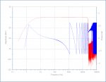
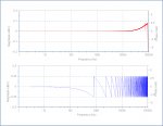
I have now measured a Driverack 480. Although it does not show the phase behavior you measured in the HF, it does show the LF "issue". I used a NI PXI-4461 at a FS of 200kHz. I removed all the transformers from my test setup. I ran the signal directly into the 4461 with no signal conditioner at all. The period of the measurement is over 5 seconds. I didn't really set the t0 that accurately so the total phase wrap is probably wrong. Picked up some noise at 60Hz. But it shows what is going on below what SMAART can tell you.
 

Attachments

  • DriveRack480.JPG
    DriveRack480.JPG
    227.5 KB · Views: 1
Re: Well, THAT's Not Gonna Fucking Work!

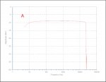
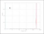
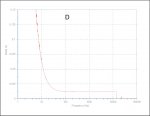
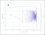
Here are the measurements made with the Lock-In Amplifier. Or Hilbert Decomposition if you will. PXI-4462 for DAQ input running at 100kHz. Signal generated with PXI-5411 from 5.0Hz to 40kHz. Reference clock generated by PXI-6653 to guaranteeing phase alignment and triggering.

(A) The figures show the directly measured Amplitude. I forgot to set the output level to 1V.

(B) Lock-In amplifier gain difference from "loopback" to DriveRack 480 output and the phase difference.

(C) The THD for 5 harmonics from the Lock-In amplifier output signal.

(D) The "Delay" as derived from the phase.

Sorry I didn't process the data at all. Segments where the value jumps to zero is where LOCK was lost due to SNR or the wavelength being too long for the maximum recording window I set.
 

Attachments

  • A_Direct dBV.JPG
    A_Direct dBV.JPG
    77.4 KB · Views: 1
  • C_LockinTHD5Harmonics.JPG
    C_LockinTHD5Harmonics.JPG
    66.6 KB · Views: 1
  • D_Delay.JPG
    D_Delay.JPG
    72.7 KB · Views: 1
  • B_LockInAmpMeasurement.JPG
    B_LockInAmpMeasurement.JPG
    109.7 KB · Views: 1
Last edited:
Re: Well, THAT's Not Gonna Fucking Work!

Mark,

Can you show us loopback on your interface? Otherwise, looks like a problem across the line. I should be able to measure a DR480 when I get back to the easy coast mid next week.

Enclosed graphic shows what I measure if I take the two XLR cables, input and output approx. 6ft a piece, and connect them together. There is also no shielding connection when I connect them like that. With my signal conditioner removed I have connected 2+ and 3- to the BNC tip and shield since the PXI-4461 connects in this fashion. The ground was telescoped from the dbx pin-1 shield connection. The shield connection is lifted on the PXI-4461 side.
 

Attachments

  • PXI4461Loopback.JPG
    PXI4461Loopback.JPG
    225.5 KB · Views: 1
Re: Well, THAT's Not Gonna Fucking Work!

I believe I have observed the similar phase behavior in the DriveRack 480. I will set my unit up tomorrow and verify.

FWIW I just measured an old Ashly Protea 4.24C processor. When you set its high and low pass filters to "off" they are indeed OFF.

And to be completely fair the latest generation dbx loudspeaker processors (at least the "pro" level) are pretty well behaved. They have done their homework for sure.