Hi Mark,
FWIW, for some reason I think that some the DBX stuff is similar to the BSS … anyway this is what the BSS omini drive compact manual says regarding phase....
A classic 2-Way crossover using just a high-pass and a low-pass filter will
always meet the criteria predicted for a given alignment. A 2-Way Linkwitz-
Riley crossover ,for example, will produce its two outputs 'everywhere in
phase', and they will acoustically combine to a flat amplitude response. The
main lobe of the polar response will also be on-axis.
When more filters are added to the crossover for more than two drivers,
however, the crossover begins to depart from the mathematical perfection of
the 2-Way case. In a 3-Way crossover, the high-pass characteristics of the mid
band will be disturbed by the phase response of the low-pass in the mid band,
and vice-versa. This results in drivers of adjacent bands being driven out of
phase, producing irregularities in the amplitude response, and pushing the
main lobe of the polar response off-axis, further aggravating amplitude
response problems in some listening positions. Although these effects may be
subtle when the crossover frequencies are well separated, 4 and 5-Way
systems can produce significant errors.
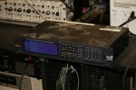
The phase compensation scheme employed in the FDS-355 analyses these
phase anomalies whenever adjustments are made, and introduces phase
adjustment into certain bands such that the phase difference between all
adjacent bands is always close to zero degrees. It will of course allow the user
to introduce intentional phase differences, using the phase and delay
parameters. The FDS-355 will not attempt to apply phase compensation if the
high and low frequencies or shapes of the adjacent bands do not match, on
the assumption that the user does not expect to produce a standard alignment.
Peter


 ~:-D~:grin:

") ~
~