60 Degree DIY Mid Hi - AKA PM60

Re: 60 Degree DIY Mid Hi

whats the best Least compromized cheaper alternative to the bms horn driver?
would the EV DL12 be an ok substitute for the bms 12?

thanks
 
Re: 60 Degree DIY Mid Hi

whats the best Least compromized cheaper alternative to the bms horn driver?
would the EV DL12 be an ok substitute for the bms 12?

thanks
I don't really think there is an alternative to the BMS compression driver, the BMS 4594 is cheaper than the HE version and to save money on amps and processing you could use the BMS passive crossover between the HF & VHF.

For this design to work you need to get the crossover frequency of the HF down to about 600 to 700Hz. Most normal compression drivers do really like to go loud that low.

The 12" is an RCF. A less costly alternative to the RCF is a B&C 12NDL76. The B&C is also an excellent speaker. If you don't mind the weight, the EVDL12X would work very well.
 
Last edited:
Re: 60 Degree DIY Mid Hi

I don't really think there is an alternative to the BMS compression driver, the BMS 4594 is cheaper than the HE version and to save money on amps and processing you could use the BMS passive crossover between the HF & VHF.

For this design to work you need to get the crossover frequency of the HF down to about 600 to 700Hz. Most normal compression drivers do really like to go loud that low.

Hi Peter,

That frequency range is pushing it a little for our 3" compression drivers, but not a problem for our 4" coil drivers. In the fall we will begin production of the DE1090TN which we introduced at Pro Light & Sound in Frankfurt: a 4" coil, 1.4" or 2" exit, inside magnet compression driver. This kind of LF corner is no problem for the DE1090TN, it saves an XO point, performance through the rest of the operating band is comparable, distortion is lower, and it's considerably lighter and less expensive. Most of the customers I run into using the BMS coaxial are not running it all that low and could replace it with one of our normal compression drivers, extensive testing in the lab and in the field has borne this out.

View attachment DE1090TN.pdf

P.S. It's not a problem for our existing DE1080TN or DE1085TN either, but those are outside magnet and physically larger. I don't know if they'll fit in your box.
 
  • Like
Reactions: Leon JEDDi Lawrence
Re: 60 Degree DIY Mid Hi

Hi Peter,

That frequency range is pushing it a little for our 3" compression drivers, but not a problem for our 4" coil drivers. In the fall we will begin production of the DE1090TN which we introduced at Pro Light & Sound in Frankfurt: a 4" coil, 1.4" exit, inside magnet compression driver. This kind of LF corner is no problem for the DE1090TN, it saves an XO point, performance through the rest of the operating band is comparable, distortion is lower, and it's considerably lighter and less expensive. Most of the customers I run into using the BMS coaxial are not running it all that low and could replace it with one of our normal compression drivers, extensive testing in the lab and in the field has borne this out.

View attachment 13007

I will have to check it out ... I had looked at the 1080 but it was only available in 1.5" ... the problem was finding a suitable 1.5" exit horn with the correct external dimensions, cut of frequency and pattern. Your spec sheet also recommend a 1KHz crossover. RCF have an ND950 1.4 that may go low enough but it does not sound as nice as the BMS 4594 or 4594HE.

The HE version I'm using has flux demodulation rings to lower distortion, its expensive but it does sound really nice.

... on another note - Your new 14NDL88 looks very interesting and the coaxial version ????
 
Re: 60 Degree DIY Mid Hi

12mm is good :)~:-)~:smile: Its also important not to change the volume between the cone and the horn entrance too much. If you reduce the volume you will get slightly more HF out of the 12"

Ok, that sways me back into the the 15mm routed 6mm, with a 6mm spacer. I little more work for sure, but I really would like 12mm, ......and that just doesn't seem doable without a spacer, even for 18mm ply.

Don (and Peter).....

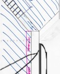
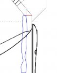
Below is a snip of what I was trying to suggest for the horn baffle....maybe it makes sense????
The red line is the angle I cut flare piece A...makes it much easier to make pieces and get good fit IMO. Also makes it easier to contemplate interchangeable for universality..
The blue stuff is a small cleat for easy alignment and fastening....

baffle sug.JPG
 
Re: 60 Degree DIY Mid Hi

on another note - Your new 14NDL88 looks very interesting and the coaxial version ????

We've had huge success with our NDL88 series woofers in 12", 14", and 15". They seem to hit the correct balance between sensitivity, LF extension, and power handling. They were designed for two way use in contemporary two way arrayable cabinets. The 14CXN76 and 14HCX76 are 3" coil coaxials on our 14" frame, but we haven't built a 3.5" coil 14CXN88 model - yet. Maybe we'll use our new 3.4" coil compression driver for the HF. No promises ;)
 
Re: 60 Degree DIY Mid Hi

Ok, that sways me back into the the 15mm routed 6mm, with a 6mm spacer. I little more work for sure, but I really would like 12mm, ......and that just doesn't seem doable without a spacer, even for 18mm ply.

Don (and Peter).....

Below is a snip of what I was trying to suggest for the horn baffle....maybe it makes sense????
The red line is the angle I cut flare piece A...makes it much easier to make pieces and get good fit IMO. Also makes it easier to contemplate interchangeable for universality..
The blue stuff is a small cleat for easy alignment and fastening....

View attachment 13008

Mark,
The reason I went with the other method was to try and have a large mating surface for the baffle to sit on piece A since I panned on making the baffles interchangeable. If you add the support cleat you show in blue then I see no reason the parts can't be modified per your drawing.
 
Re: 60 Degree DIY Mid Hi

Mark,
The reason I went with the other method was to try and have a large mating surface for the baffle to sit on piece A since I panned on making the baffles interchangeable. If you add the support cleat you show in blue then I see no reason the parts can't be modified per your drawing.

Hi Don, yes that makes total sense.
And I don't mean to belabor this....I can easily make the mods i have in mind....I'm just thinking there is an opportunity to make it easier for others...

It seems to me, the stepped depth of the cabinet allows the HF horn baffle board to span the full exterior width, very easily. And do so with out any bevels.
Below is maybe a better depiction at what I'm getting at.
The blue cross hatching represents the sides.....

Try 1.JPG

Sorry for a drawing so crude....

But i like this because now there aren't any angles on the baffle ends, the angle on flare piece a is now 40 degrees instead of 50 (much easier w table saw, and probably best of all ......the baffle board is one piece.
I like a little cleat as much for an alignment aid as anything, but it can also be used to help facilitate the interchangeable route . But it's entirely optional because the baffle board can screw straight into both sides....

Again, just trying to throw out something that might make it easier to build...
 
Re: 60 Degree DIY Mid Hi

While drawing up the box in Sketchup, I found and error in the XT1464 baffle dimensions. I've corrected it and included the PDF here.
Also, here is a screen shot of the box in Sketchup so that file is also available.

Mark's points about the baffle design are spot on but this may be one of those items left up to the individual builder. I could possibly make a revision to the drawings but that would have to be as time permits.
 

Attachments

  • diy mid-high 8-6-15a.pdf
    diy mid-high 8-6-15a.pdf
    203.6 KB · Views: 138
  • Screen Shot 2015-08-06 at 4.58.59 PM.png
    Screen Shot 2015-08-06 at 4.58.59 PM.png
    53.4 KB · Views: 107
Re: 60 Degree DIY Mid Hi

Don,

How much material are you leaving at the outside edges of the ports? They look flush cut on Part A's diagram. Would the piece not be stronger (with less chance of vibration/rattling) if those ports were kicked in 19 or so mm? Would that negatively impact performance?

Dave
Dave, Peter explained to me that by having the ports as close as possible to the horn wall you gain effective length to the port.
On my build I left about 2-3mm so the edge of part A would not blow out when being drilled.
Peter could answer how much the performance would vary with the ports inset by the amount your suggesting.
 
Re: 60 Degree DIY Mid Hi

Don,

How much material are you leaving at the outside edges of the ports? They look flush cut on Part A's diagram. Would the piece not be stronger (with less chance of vibration/rattling) if those ports were kicked in 19 or so mm? Would that negatively impact performance?

Dave
When there is another input into the horn throat/mouth the conventional wisdom is that the best place to do that is on junction between the horizontal and vertical walls. This should have the least impact on the horns normal behaviour.

The position of the port in terms of distance from the horn mouth is also important. In this case it can be modelled in horn response and should be close to the mouth.
 

Attachments

  • horn port location.jpg
    horn port location.jpg
    88.4 KB · Views: 57
Last edited by a moderator:
Re: 60 Degree DIY Mid Hi

I finally had a chance to test the box with the 90 deg horns installed. Again I think they sound fantastic and the horizontal coverage is much wider than the 60. Here is a capture of the traces. It was kind of windy but everything held together well.
 

Attachments

  • 90 deg horn.jpg
    90 deg horn.jpg
    308 KB · Views: 62
Re: 60 Degree DIY Mid Hi

Hi Peter,

That frequency range is pushing it a little for our 3" compression drivers, but not a problem for our 4" coil drivers. In the fall we will begin production of the DE1090TN which we introduced at Pro Light & Sound in Frankfurt: a 4" coil, 1.4" or 2" exit, inside magnet compression driver. This kind of LF corner is no problem for the DE1090TN, it saves an XO point, performance through the rest of the operating band is comparable, distortion is lower, and it's considerably lighter and less expensive. Most of the customers I run into using the BMS coaxial are not running it all that low and could replace it with one of our normal compression drivers, extensive testing in the lab and in the field has borne this out.

View attachment 13007

P.S. It's not a problem for our existing DE1080TN or DE1085TN either, but those are outside magnet and physically larger. I don't know if they'll fit in your box.

Interesting CD, you say similar performance, how do you compensate for the almost 10 dB higher sensitivity on the 4594ND/HE? I'm trying to understand the power handling figures but can't really separate them, on the DE1090TN paper you linked it says "continuous power handling"(Is this equivalent to RMS value?) while the 4594 has got AES published on its paper, can the B&C take that much more energy to compensate for the lower sensitivity? Will this also be available in Europe by this fall?
 
Re: 60 Degree DIY Mid Hi

Interesting CD, you say similar performance, how do you compensate for the almost 10 dB higher sensitivity on the 4594ND/HE? I'm trying to understand the power handling figures but can't really separate them, on the DE1090TN paper you linked it says "continuous power handling"(Is this equivalent to RMS value?) while the 4594 has got AES published on its paper, can the B&C take that much more energy to compensate for the lower sensitivity? Will this also be available in Europe by this fall?

I will up date this tomorrow ... however the BMS on a 60 x 50 horn is more like 114 dB/w/m and 112dB/w/m on a 90 x 50 ... but its more complicated than that...
.
I suspect the B&C is a very tough driver and will have a similar output over a limited bandwidth.
 
Re: 60 Degree DIY Mid Hi

Thanks Peter! If this project could be a little bit more affordable due to cheaper parts I think it could potentially attract a lot of more people(including me=) btw did you experiment with IIR settings for these cabs? I remember you said FIR are recommended/mandatory for these cabs in the other 90° thread which made me wonder, does these cabs react differently to FIR vs IIR compared to other top cabinets, or was it merely you prefering FIR in most situations thus advocating for it?
 
Last edited:
  • Like
Reactions: Leon JEDDi Lawrence
Re: 60 Degree DIY Mid Hi

Interesting CD, you say similar performance, how do you compensate for the almost 10 dB higher sensitivity on the 4594ND/HE? I'm trying to understand the power handling figures but can't really separate them, on the DE1090TN paper you linked it says "continuous power handling"(Is this equivalent to RMS value?) while the 4594 has got AES published on its paper, can the B&C take that much more energy to compensate for the lower sensitivity? Will this also be available in Europe by this fall?
This is EXACTLY where trying to use a "simple single number" to describe performance can get you in all kinds of trouble.

With HF drivers, you HAVE to have them mounted on the same horn to get equal curves.

Then you HAVE to look at the curve-NOT a single number to figure out how they compare.

If one manufacturer is using a single high peak in the response and another is using more of an average, then you will get very different numbers for exactly the same curve

For example. Look at the CURVE of the driver that Bennett posted. It is rated at 108.5dB, but has a peak 5dB or higher above that.

I have compared/measured some of B&C's better drivers to the BMS units.

On the same horn, they are very equal in sensitivity. The BMS units have a higher sensitivity up high.

And then there is the "rated power" vs what they can actually handle.

I will not say-or go into details- but some drivers fail much earlier than others-even when rated at the same or higher power.

You have to do destructive testing under the same conditions to get usable results.

I have destroyed thousands of dollars of diaphragms doing such tests.

Things are not always as they seem or appear on paper-ESPECIALLY when using the "simple numbers". You can get very WRONG results or expectations.
 
Re: 60 Degree DIY Mid Hi

For this project to work the LF horn needed to get down to about 80Hz - 100Hz. To do that it had to be about 2 feet long and it had to be bent to make the box small enough to be stick mountable.

The LF horn exits top and bottom with the HF horn in the middle. This has vertical directivity implications for the mid range and the bends in the horn limits the quality of the audio above about 800Hz. This meant it was important to be able to get the compression driver to go low – 600Hz to 700Hz.


Note : All the drivers in this design operate in their piston range and there is more or less no cone break-up.


Compression Driver Selection


The BMS driver was designed to operate as low as 300Hz. Above 500Hz the mid range has a peak rating of 1000W and an efficiency of about 110 dB (on a 60 x 40 horn); it maintains at least this efficiency all the way to 20kHz.

In terms of distortion the standard 4594 initially doesn't look like anything special, however the HE version I used has flux demodulation rings to lower the distortion. It’s also very important to understand how we perceive distortion. Some distortions are more noticeable than others; some are too high to be heard and others can be masked by the fundamental tone/frequency. The masking occurs for the same reasons as we can delete a soft signal adjacent to a loud fundamental in music compression algorithms.

In simple terms second harmonic distortion is not as objectionable as third harmonic and sub harmonic distortions. The BMS designs have low third and sub harmonic distortions.
Sub harmonic distortions are generally caused by cone breakup and also have an effect on shape of the wave front. http://www.beyma.com/uploads/descargas/1352741021.pdf

The horn flare can also contribute to distortion and it is on of the reasons that the RCF HF950 and XT1464 were selected. (see the note on the XT1464 specifications)

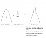
The BMS is a two-way design which has some advantage for music reproduction. Instead of thinking in terms of one frequency x power handling x efficiency, think in terms of music, dynamics and energy over the whole audio spectrum. The LF part of the compression driver can be going flat out and then the VHF can add more energy to that, producing very substantial peaks. See my sketch below where I have used voltage as an analogy to sound pressure.

I suspect if you used a large 4” diaphragm compression driver in combination with a separate VHF driver you will get similar results to the BMS. This is what my friend does with his commercial cinema designs and they sound wonderful.

By using the BMS there is substantial weight and space savings compared to using a 4' diaphragm compression driver or even a 6" - 8" mid plus a VHF driver. This is particularly important in this case where I was trying to keep the weight below 35 kgs.

With the DIY everything exits the same horn from above about 600Hz. The HF horn is also located in the centre of the LF horn. The end results is that DIY behaves very much like a perfect point source … and I’m sure you are aware of all the advantages of this, just ask Ivan
J


In addition to Bennett’s suggestion of the new 1090, here are some other drivers that that may work. I don’t think you will get that studio monitor like sound quality out of them unless you use a separate VHFdriver or a Beryllium diaphragm variant. FWIW the 4594HE was initially developed for high end studio monitor applications. Except for the Beryllium alternatives they will all be cheaper than the 4594
J.


http://www.eighteensound.it/PRODUCTS/Products/CatID/3/ProdID=152#.Vca5CmkiPDA
http://www.rcf.it/en_US/products/precision-transducers/neodymium-compression-drivers/nd950-1.4
http://www.rcf.it/en_US/products/precision-transducers/neodymium-compression-drivers/nd950-1.4 - I think this is available in 1.4” and with a Beryllium diaphragm.
http://www.beyma.com/products/compressiondrivers/1CP85ND8
 

Attachments

  • HF +VHF.jpg
    HF +VHF.jpg
    73 KB · Views: 58
Last edited:
  • Like
Reactions: Leon JEDDi Lawrence
Re: 60 Degree DIY Mid Hi

Interesting CD, you say similar performance, how do you compensate for the almost 10 dB higher sensitivity on the 4594ND/HE? I'm trying to understand the power handling figures but can't really separate them, on the DE1090TN paper you linked it says "continuous power handling"(Is this equivalent to RMS value?) while the 4594 has got AES published on its paper, can the B&C take that much more energy to compensate for the lower sensitivity? Will this also be available in Europe by this fall?

Hi Ossian, others have posted great answers but I wanted to get back to you as well.

BMS don't make it clear on what horn they have measured the sensitivity numbers for any of their compression drivers, so we have been unable to replicate them. On any of our horns, we measure sensitivity averaged across the stated usable frequency range of the driver similar to our flagship 3" or 4" coil compression drivers. As Ivan notes everyone's application is different, so it is critical to test to destruction in order to see which driver can deliver more real world SPL.

Our spec sheets list both AES and "continuous" (2x AES) power, the latter is intended to be used as an amplifier sizing guide: e.g. the DE980TN will likely be well matched by an amplifier that can deliver about 220 watts. Nothing magic about power handing in a compression driver - there's no active cooling, thermal mass is what it is, and the coils are very short and light, so power handing is more or less dictated by the diameter of the coil. Of course some coil suppliers can deliver better power handling than others, we have only been able to qualify two HF coil suppliers in the world.

We hope to have first samples of the DE1090TN and DE990TN available to our OEM customers in the late fall, and probably will begin manufacturing for distribution around the end of the year.