FIR filters

Within reason you need to flatten the pass-band past the crossover point so that when you apply the crossover it rolls off with the exact slope and shape (of the crossover type you are using) for about the first 12dB.

The other trick you can do on the low section of the DIY is EQ it to naturally look like 12 dB Butterworth slope at 100Hz and then add a 12 Butterworth 100Hz crossover, the end result will be a 24 dB LR slope. Two 12 dB Butterworth crossovers in series = 24 dB LR.

.... also if you want to use the DIY at loud volumes I would use 24 dB crossovers.


Hi Peter, yes thx, you describe my goal...to have magnitude response roll off ala textbook x-over shape, for at least the first -12db. I'll try the BW EQ / BW12 x-over combo...guess it just comes down to easiest way to keep phase flat there.. (ie fewest taps)

I use at least 24db on the DIY...I was using the 12 db example above just to help show contrast between an expected roll off (shallower) than the steepness generated
 
Hi Mark,

With the MiniDSP before the crossovers, I'd suggest tuning the system with just the IIR crossovers (and any other IIR output EQ) in place, then take a full-range measurement and import that into FIR Designer. You can then create just one FIR filter for the whole system, and any magnitude and phase adjustments or corrections you make will affect the combined acoustic response of both drivers.

Best regards,
Michael


One chaining strategy I am pursuing though, is using FIR in front of IIR crossovers, a channel of FIR for each IIR channel per driver.
 
Hi Mark,

With the MiniDSP before the crossovers, I'd suggest tuning the system with just the IIR crossovers (and any other IIR output EQ) in place, then take a full-range measurement and import that into FIR Designer. You can then create just one FIR filter for the whole system, and any magnitude and phase adjustments or corrections you make will affect the combined acoustic response of both drivers.

Best regards,
Michael

You must take care with that approach – each driver must behave correctly in terms of amplitude at time and it must do that beyond the crossover points.

You can fix things that are in the middle pass-band with a global filter, but where the correction will impact the adjacent band you can have an issue.

I will try and explain a little more – If you have a linear system and it has a peak in the response some where you will see a corresponding behaviour in the time domain … waterfall plot or whatever you use. If you apply the correct EQ to fix the peak you also fix things in the time domain.

If this occurs near or at the crossover point you are effectively modifying two pass-bands. One that may not need correction; and the one that does need correction will not be corrected enough. If they summed perfectly all would be well, but usually that’s not the case.

The results can be an amplitude response that’s looks fine but there can be audible issues in the time domain.
 
I agree, what's important is how the drivers interact, especially beyond the crossover frequency, and so it's important to make driver-unique adjustments so that they play nicely together. Whether that's done using independent FIR's (plus crossovers) for each driver, or done with different IIR's (EQ and crossovers) on each driver + a global FIR correction filter, shouldn't make a difference. The smarts are in how we make and interpret the driver measurements.

If we both phase match two drivers (or horn and driver) and suppress out of band oddities using IIR filters independently for each driver, and combine this with a FIR filter to linearise the phase of the combination, the result is the same (assuming the same magnitude profiles for each driver) as linearising the phase of each driver independently using FIR filters plus linear phase crossovers. The workflow of one may be easier than the other, depending on experience and taste. In both cases, temporal issues are addressed by the phase linearisation in the FIR. Remember, phase and time are duals of each other.

You must take care with that approach – each driver must behave correctly in terms of amplitude at time and it must do that beyond the crossover points.

You can fix things that are in the middle pass-band with a global filter, but where the correction will impact the adjacent band you can have an issue.

I will try and explain a little more – If you have a linear system and it has a peak in the response some where you will see a corresponding behaviour in the time domain … waterfall plot or whatever you use. If you apply the correct EQ to fix the peak you also fix things in the time domain.

If this occurs near or at the crossover point you are effectively modifying two pass-bands. One that may not need correction; and the one that does need correction will not be corrected enough. If they summed perfectly all would be well, but usually that’s not the case.

The results can be an amplitude response that’s looks fine but there can be audible issues in the time domain.
 
Last edited:
As you say, what's important is how the drivers interact and so it's important to make driver unique adjustments so that they play nicely together. Whether that's done using independent FIR's (with crossovers) for each driver, or done with different IIR's (EQ and crossovers) on each driver + a global FIR, shouldn't make much difference. The smarts are in how we make and interpret the driver measurements.
I think what Peter Morris is trying to say is that: only IIR/EQ per driver does not always work nicely. If you don't have FIR per driver, than you have (much) less options to correct the (out of band) phase behaviour of the individual drivers. You cannot correct the phase per driver with a global FIR filter...
 
Hi Peter,

Yep, I understand.

>> If you don't have FIR per driver, than you have (much) less options to correct the (out of band) phase behaviour of the individual drivers.
With detailed IIR all-pass and parametric filters (e.g. Lake processing), one can do fairly complex out-of-band magnitude adjustments and phase matching of the two drivers. A global FIR can then undo the phase that's been added by those IIR's.

>> You cannot correct the phase per driver with a global FIR filter
That's right, but I don't think first linearising the phase of individual drivers needs to be the primary goal. IMHO the goals are suppressing out-of-band oddities and phase matching over the most of the desired coverage angle. If that is achieved, then a single global FIR linearisation filter can work fine.

Specifically for a horn, correcting some of the horn reflections via phase linearisation can be done either on the horn alone or in a global filter. The end result will be the same for the horn frequency range above crossover.

The notion of individually linearising the drivers first is fine, but it can be hard to know how far to go into the out-of-band areas. Too far in the low end, and the linearisation comes at the cost of increased latency in the FIR filters and possibly some discontinuities in the mag/phase of the filters. Going just far enough keeps the FIR filters as short as necessary to get the job done. Doing a mag & phase match the old way first and FIR correcting the aggregate, I think, may be easier and may result in slightly lower overall latency. (I could be wrong. :) )

I think what Peter Morris is trying to say is that: only IIR/EQ per driver does not always work nicely. If you don't have FIR per driver, than you have (much) less options to correct the (out of band) phase behaviour of the individual drivers. You cannot correct the phase per driver with a global FIR filter...
 
Last edited:
Hi Peter,
Yep, I understand. I'm trying to dispel those notions somewhat.
>> If you don't have FIR per driver, than you have (much) less options to correct the (out of band) phase behaviour of the individual drivers.
With detailed IIR all-pass and parametric filters (e.g. Lake processing), one can do complex out-of-band magnitude adjustments and phase matching of the two drivers. A global FIR can then undo the phase that's been added by those IIR's.
>> You cannot correct the phase per driver with a global FIR filter
That's right, but I don't think first linearising the phase of individual drivers needs to be the primary goal. IMHO the goals are suppressing out-of-band oddities and phase matching over the most of the desired coverage angle. If that is achieved, then a single global FIR can work fine.
The notion of individually linearising the drivers first is fine, but it can be hard to know how far to go into the out-of-band areas. Too far, and the linearisation comes at the cost of increased latency in the FIR filters. Going just far enough keeps the FIR filters as short as necessary to get the job done. Doing a mag & phase match the old way first and FIR correcting the aggregate, I think may result in slightly lower overall latency. (I could be wrong. :) )

Hi Michael, for me this post hits the nuts of it....and that is, what's the easiest way to get it done right....
I gotta start by saying I'm totally sold on the driver-by-driver approach...


I understand that correcting driver by driver is a minimum phase effort.
But elecrtical x-overs filters aren't...(if i understand correctly).

I have experienced a huge amount of time consuming trial and error trying to find x-over filter types, orders, and points that gave the desired acoustic center.
Just for on-axis....move off and it's a whole new set of trial and error.
And IMHO, it's mostly due to sloped phase......

So for me, to get magnitude and phase flat driver-by-driver before I go to x-over, shortcuts all kind of time and effort....
If I can get mag and phase flat through, and maybe even past the critical region, simple symmetric LR works.....and then I can simply shift x-over freq for off-axis response, without any other redo.

And yes, I hear you re latency, and the temptation to over do mag and phase flattening too far out of band...(where it won't work anyway!)
I begin with all the taps I've got...

I can see from measurement when out-of-band isn't responding...that's the first place to let go of taps.
Then I just start chopping taps until I reach acceptable intersection of latency and SQ.
This has been much easier for me than developing a good IIR crossover for on and off axis....something I have yet to accomplish...

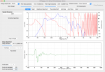
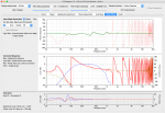
Here's a shot of the DIY60 using that approach. Latency is still high in the upper 20ms...but my tap axe is still swinging :)
Best and thx, Mark


Attachments

  • DIY#2c.JPG
    DIY#2c.JPG
    169.2 KB · Views: 10
Hi Peter,
Yep, I understand. I'm trying to dispel those notions somewhat.
>> If you don't have FIR per driver, than you have (much) less options to correct the (out of band) phase behaviour of the individual drivers.
With detailed IIR all-pass and parametric filters (e.g. Lake processing), one can do complex out-of-band magnitude adjustments and phase matching of the two drivers. A global FIR can then undo the phase that's been added by those IIR's.
>> You cannot correct the phase per driver with a global FIR filter
That's right, but I don't think first linearising the phase of individual drivers needs to be the primary goal. IMHO the goals are suppressing out-of-band oddities and phase matching over the most of the desired coverage angle. If that is achieved, then a single global FIR can work fine.
The notion of individually linearising the drivers first is fine, but it can be hard to know how far to go into the out-of-band areas. Too far, and the linearisation comes at the cost of increased latency in the FIR filters. Going just far enough keeps the FIR filters as short as necessary to get the job done. Doing a mag & phase match the old way first and FIR correcting the aggregate, I think may result in slightly lower overall latency. (I could be wrong. :) )

Hi Michael, for me this post hits the nuts of it....and that is, what's the easiest way to get it done right....
I gotta start by saying I'm totally sold on the driver-by-driver approach...


I understand that correcting driver by driver is a minimum phase effort.
But electrical x-overs filters aren't...(if i understand correctly).

I have experienced a huge amount of time consuming trial and error trying to find x-over filter types, orders, and points that gave the desired acoustic center.
Just for on-axis....move off and it's a whole new set of trial and error.
And IMHO, it's mostly due to sloped phase......

So for me, to get magnitude and phase flat driver-by-driver before I go to x-over, shortcuts all kind of time and effort....
If I can get mag and phase flat through, and maybe even past the critical region, simple symmetric LR works.....and then I can simply shift x-over freq for off-axis response, without any other redo.

And yes, I hear you re latency, and the temptation to over do mag and phase flattening too far out of band...(where it won't work anyway!)
I'm beginning tuning with all the taps I've got...

I can see from measurement when out-of-band isn't responding...that's the first place to let go of taps.
Then I just start chopping taps until I reach acceptable intersection of latency and SQ.
This has been much easier for me than developing a good IIR crossover for on and off axis....something I have yet to accomplish...

Here's a shot of the DIY60 using that approach. Latency is still high in the upper 20ms...but my tap axe is still swinging :)
Best and thx, Mark


Hi Peter,

Yep, I understand.

>> If you don't have FIR per driver, than you have (much) less options to correct the (out of band) phase behaviour of the individual drivers.
With detailed IIR all-pass and parametric filters (e.g. Lake processing), one can do fairly complex out-of-band magnitude adjustments and phase matching of the two drivers. A global FIR can then undo the phase that's been added by those IIR's.

>> You cannot correct the phase per driver with a global FIR filter
That's right, but I don't think first linearising the phase of individual drivers needs to be the primary goal. IMHO the goals are suppressing out-of-band oddities and phase matching over the most of the desired coverage angle. If that is achieved, then a single global FIR linearisation filter can work fine.

Specifically for a horn, correcting some of the horn reflections via phase linearisation can be done either on the horn alone or in a global filter. The end result will be the same for the horn frequency range above crossover.

The notion of individually linearising the drivers first is fine, but it can be hard to know how far to go into the out-of-band areas. Too far in the low end, and the linearisation comes at the cost of increased latency in the FIR filters and possibly some discontinuities in the mag/phase of the filters. Going just far enough keeps the FIR filters as short as necessary to get the job done. Doing a mag & phase match the old way first and FIR correcting the aggregate, I think, may be easier and may result in slightly lower overall latency. (I could be wrong. :) )

Hi Michael,

I don’t think we are in any disagreement on this issue. My comment was - you have to be careful, not that you can’t do that.

I will give you an example … I did a lot of work developing the FIR settings for Turbosound's Flex. The IIR settings didn’t sound too good. The Turbosound 10" “Bass Device” or whatever they called it had two peaks in the response of about 10dB, one at 500Hz and another at 800Hz cause by some horn loading and a band-pass resonance. It crossed over at about 575Hz.

What they did was match the phase and amplitude at the crossover and then apply a global filter to the input at 500Hz to flatten the peak. The amplitude response was flat but it always sounded honky at 500Hz and 800Hz. If you pulled 500Hz out on the graphic you could fix the honk but then there was something missing
.
The solution was to remove both peaks in the pass-band and then apply the crossover and everything sounded and measure great. If the drivers and horn all summed perfectly there would not be an issue, but they don't.

The trick to control temporal issues Dave Gunness style is to have the behaviour of the correcting electronic filter being exactly equal and opposite that of the resonance in the mechanical system you are trying to correct.

When those issues are out of band it’s not so critical so an IIR filter(s) is usually fine.

FWIW my settings for the DIY and the Flex use a combination of FIR and IIR filters to minimize latency. For the Flex I was able to do a linear phase crossover and EQs with only 2.5ms of FIR time.
 
FWIW I'm in the process of implementing a response averaging import mode for FIR Designer. i.e. loading a directory of measurement files and providing controls for averaging the measurements, deprecating outliers, specifying the frequency range of interest and more. (At the moment the application presumes that the user has already averaged multiple measurements, if they wish to, to create the single imported measurement.)

.... Just for on-axis....move off and it's a whole new set of trial and error. ...
 
Last edited:
.... The Turbosound 10" “Bass Device” or whatever they called it had two peaks in the response of about 10dB, one at 500Hz and another at 800Hz cause by some horn loading and a band-pass resonance. It crossed over at about 575Hz.

What they did was match the phase and amplitude at the crossover and then apply a global filter to the input at 500Hz to flatten the peak. The amplitude response was flat but it always sounded honky at 500Hz and 800Hz. If you pulled 500Hz out on the graphic you could fix the honk but then there was something missing
.
The solution was to remove both peaks in the pass-band and then apply the crossover and everything sounded and measure great.

Interesting. Makes sense. Did I hear that they then used your presets?
 
Last edited:
Interesting. Makes sense. Did I hear that they then used your presets?

There was actually an article on Turbo’s site about it, but it’s now been removed. The tricky bit was maintaining directivity through the Mid / Hi crossover. It’s not determined the horn shape, but the phase and amplitude between the HF and the two MF exits / entry into the horn flare.

FWIW ....from some of the things I learnt developing the DIY I have since developed some further improvements to the Flex settings.
 
Last edited:
Regards the MiniDSP processors, they import binary 32bit floating point data so on the Export tab, select "Binary file (32bit, float)."

FIR Designer 1.4 is now available. I've added import support for EASERA ETM measurement files (in addition to SysTune STO files and various TXT files, including from SMAART). Details at:
https://eclipseaudio.com.au/fir-designer/release-notes/

(I'm still working on arbitrary number of filter prototypes for the Mag Adjust and Phase Adjust tabs, multi-measurement import averaging and other previously mentioned ideas. Feature requests welcome!)
 
Hi Mark,

With the latest updates in Version 1.5, I've come up with some example screenshots which might help.

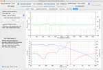
Lets say after filtering, you want the mid driver to have a response of LR24 HPF minimum phase at 100 Hz and LR24 LPF linear phase at 650 Hz.

In FIR Designer,
- choose the "Direct Design" mode
- set two of the filters on the Magnitude Design tab (one to Min LRHPF 4th order & another to Lin LRLPF 4th order)
- set the filter delay and length fairly large so there is negligible error from windowing (e.g. 2048 and 4096 samples)
- export (e.g. to 24 bit wav file.)

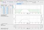
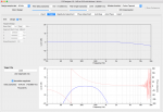
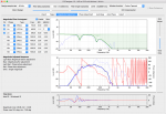
Mid_w_LR12_MinLin_Ref1.png Mid_w_LR12_MinLin_Ref2.png Mid_w_LR12_MinLin_Ref3.png

This file will be the "Target"

In FIR Designer
- In the menu, select Project -> New
- Go to the Target tab, select File and Load the above WAV file. Set the delay to minus the filter delay from Direct Design above. (e.g. -2048 samples)
- Go to the Import tab, load your measurement, then take a look at the way I've configured the settings on the all the tabs.
- The result is you have a FIR filter that will filter the driver to meet your target magnitude and phase response, including crossovers, down to -12 dB on the sides or a little lower.

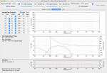
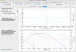
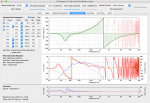
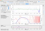
Mid_w_LR12_MinLin_Eg1.png Mid_w_LR12_MinLin_Eg2.png Mid_w_LR12_MinLin_Eg3.png Mid_w_LR12_MinLin_Eg4.png Mid_w_LR12_MinLin_Eg5.png Mid_w_LR12_MinLin_Eg6.png Mid_w_LR12_MinLin_Eg7.png

I'll email you the files too.

Best,
Michael

Hi Michael, Loving the auto-mag and phase.......(been manual only in rePhase........)
After I've imported a speaker measurement, done auto mag, done auto phase, ......how do I then overlay a crossover filter (via the Mag Adj tab?
And see final summed results?
No problem building crossover, just can't put it together with corrected mag and phase...
Thx, Mark
 
Last edited:
Hi Mark,

With the latest updates in Version 1.5, I've come up with some example screenshots which might help.


I'll email you the files too.

Best,
Michael

Hey Michael, this is very nice, thank you. And when I checked email, I saw something was blocking and I missing seeing a previous email from you...sorry there mate !

I will download Version 1.5, and definitely go through what you're showing me.

Will post here, maybe with bms 4594he driver attempts as well......or send questions direct to you, whichever appears more appropriate.

Thanks again, and best, mark

 
There was actually an article on Turbo’s site about it, but it’s now been removed. The tricky bit was maintaining directivity through the Mid / Hi crossover. It’s not determined the horn shape, but the phase and amplitude between the HF and the two MF exits / entry into the horn flare.

FWIW ....from some of the things I learnt developing the DIY I have since developed some further improvements to the Flex settings.

Hi peter

Are your further improvements included in the fir filters currently available on the turbosound website?

Also, do you have the filters as .csv? For using them in a soundweb processor
 
Hi peter

Are your further improvements included in the fir filters currently available on the turbosound website?

Also, do you have the filters as .csv? For using them in a soundweb processor

No the improvements are not included. Basically the improvements address some out of band resonance issues of the 10" drivers around 800Hz.

I have CSM files ... what are you interested in, the 75 degree box or the 100 degree box?
 
Cool:) I´m interested in both

csm, so lake module files?

Do you have the coeffisients as a csv file as well?
I´d be interested in testing your FIRs at a venue here in bergen where they have 4 75degree boxes over 2 100degree boxes, processed with soundweb and powered by lab c-series amps
TSW-218 subs
 
Slightly off topic here, but could somebody suggest a good audio theory book or books to read in order to understand the conversations in this thread better? This could be the wrong place for such a question but i figure as anybody in this thread must have read such books, it is kind of the right place to ask as well.