New DIY Mid High (90deg) - AKA PM90

Did anyone shoot a unprocessed ground-plane measurement of the RCF LF section? I was looking at Andy's Impedance measurement up there a couple posts, and interested to see SPL Frequency Response.

LF ..... https://soundforums.net/filedata/fetch?id=154012

FWIW here is the HF section ... Post 267 ... https://soundforums.net/filedata/fetch?id=154113

It shows the plot with the HF90 and the Eighteen Sound XT1464 ... also there is a plot of a Krix Horn with the 4594
 
Last edited:
Anyway I tried it on a Powersoft dsp amp after converting Bandwith to Q, but the sound was not right.

Hi Andy,

It looks like this could only be a small part of your difficulties, but converting BW to Q is not enough to transfer settings between DSP platforms. I wrote an article (668KB PDF) and made a presentation (827KB PDF) about this.
 
  • Like
Reactions: Ste Von
Andy, for subs I'm using either JTR orbit shifters or labhorns.
I wouldn't be concerned with the level difference between the mid and coax... the coax efficiency overbalances the impedance difference.
The Rational RTA-420 mic, or the Dayton EMM-6 which comes with a calibration file, or even the ECM800, would be my picks...
 
Did anyone shoot a unprocessed ground-plane measurement of the RCF LF section? I was looking at Andy's Impedance measurement up there a couple posts, and interested to see SPL Frequency Response.

Mark D.

I did a nearfield(0cm from baffle) on ground no dsp, not 2.83v. The peaks at ~375 and ~525 gets stronger with distance I think.
- I need to find the correct measurement and will update asap.

EDIT: Sorry I see this post was answered
 
Last edited:
Hi Andy,

It looks like this could only be a small part of your difficulties, but converting BW to Q is not enough to transfer settings between DSP platforms. I wrote an article (668KB PDF) and made a presentation (827KB PDF) about this.

Hi Bennet.

Thank you for the papers. Very interesting reading.

When transferring the Lab DSP settings referenced earlier, I used the an online tool from Sengpiel audio: http://www.sengpielaudio.com/calculator-bandwidth.htm , to convert from bandwidth to Q.

After reading your papers I get it, that there are other factors, some of which are depending on the DSP hardware/architecture? This is very interesting stuff.

I have also used the method of 'reading out' the DSP setting from a 'certain' amp for a certain speaker and was able to manually replicate to Powersoft amps, by visually tailoring the FR curve. The result was acceptable. The copied DSP settings are still missing the phase correction part - which is next on the 'how to' list.

You are mentioning limiter behavior, which is also something I need to get into. I wonder if you want to copy from one amp to another, there is any other way but to push the amp (with power resistors connected) and measure with an L-PAD?

Further I am guessing that some amps like d&b audiotechnik D12 etc. are using dynamic EQ?

All in all, I reckon if you always measure the results of your DSP settings before using, it cannot go really wrong.

I need to read more about all this.


Andy, for subs I'm using either JTR orbit shifters or labhorns.
I wouldn't be concerned with the level difference between the mid and coax... the coax efficiency overbalances the impedance difference.
The Rational RTA-420 mic, or the Dayton EMM-6 which comes with a calibration file, or even the ECM800, would be my picks...

Mark.
I always wanted to hear the JTR Orbit shifter subs :0) but I don't know of anyone here in Denmark who have them.
The LAB subs are impressive especially in greater numbers :0)

I am using Xoc1 TH-18 tapped horns with B&C 18SW100. They are good to 35Hz, but I could actually do with subs that goes even lower. I am considering a build of single 18 reflex tuned very low.

Are you using your tops as speaker on a stick on top of your subs, or ?
 
Andy, nice subs you have ! If I were thinking more DIY subs right now, it would either be those or the keystones.....

I use the tops both on sub and on stick; great results either way, just takes a little more fiddling with alignment when up on a stick.

I think as you spend more time with the DIY90 you'll keep getting better and better sound. As everyone who has built either of the DIYs comments, they are unusually sensitive to small eq changes....something I've learned to count as a virtue.
Right now, after a years' plus learning how to tune, I have to say the DIY has the best combination of dynamics and revealing sound I've heard from any speakers.
 
  • Like
Reactions: Andy Turner
Hello,

We also want to build the DIY Mid High 90.
We have read the whole thread and where thrilled how much valuable information is in it.

We will try to build this box for using it in a stack with other sub/mid-bass horn speakers.

The plans are clear so far.

The only thing is which isn't 100% understandable for us the spacing between the speaker and the baffle.
In the plans you you can see a ring, a kind of spacer.
How far away should be the mounting surface of the speaker from the baffle?

Xmax is about 7mm...

 
The only thing is which isn't 100% understandable for us the spacing between the speaker and the baffle.
In the plans you you can see a ring, a kind of spacer.
How far away should be the mounting surface of the speaker from the baffle?

Xmax is about 7mm...

My understanding is Xmax is not the physical limit of how far the cone can travel. There are other variables that define that. From what I recall, Peter designed his to have a minimum of 10mm clearance. I went with about 12mm. So far I have not had any issues with them bottoming out.
I used a 5mm spacer plus a 7mm relief removed from the baffle face with a router.
 
Peter - What is the double 14" version that you mentioned in #488?
Thanks!
Gary.

Hi Garry,

It uses a larger proprietary 90 x 40 horn, and two 14” B&C drivers. The 14s are in a seal enclosure with a small chamber in front of each of the 14s, I guess you could say its a 4[SUP]th[/SUP] order band pass with the front chamber tuned to about 500-600 Hz. The 14s exit in 2 slots above and below the horn. This helps control vertical directivity.

The end result is better pattern control than the double 12, it sounds a little better, but it is larger and weighs 5 Kgs more. It does not go any louder than the double 12.
 
My understanding is Xmax is not the physical limit of how far the cone can travel. There are other variables that define that. From what I recall, Peter designed his to have a minimum of 10mm clearance. I went with about 12mm. So far I have not had any issues with them bottoming out.
I used a 5mm spacer plus a 7mm relief removed from the baffle face with a router.

In my CNC routed version I like to use an 18mm baffle for the 12" parts and route it halfway to 9mm depth, but I could easily increase it to 10.5mm for extra room. What do you all think, is it worth it?
 
My understanding is Xmax is not the physical limit of how far the cone can travel. There are other variables that define that. From what I recall, Peter designed his to have a minimum of 10mm clearance. I went with about 12mm. So far I have not had any issues with them bottoming out.
I used a 5mm spacer plus a 7mm relief removed from the baffle face with a router.

Hey

XMech is the parameter that deals with the physical limit of the cone's movement, the mechanical distance it can travel before metal starts to hit metal.

XMax is more to do with the movement within the magnetic field. Though i'm sure there will be an exact technical definition, its basically the amount it can travel while staying in the main part of the magnetic field and providing a linear response.

As you travel beyond XMax and towards Xmech, you would start to see more distortion and more non-linearity added into your signal, and the response of the driver would drift further and further away from the driver specs, and the predictions and frequency responses generated by these.

k

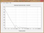
Here is the calculated displacement at 1300 watts - approx. 10mm. X mech / damage is 39mm peak to peak on the RCF.

Assuming a 100Hz LR crossover the max displacement would approx. 5mm provided things are set up / limited correctly. This is just within the linear Xmax range of 5.5mm.

Accordingly I would suggest you need at least 10mm of clearance - Max's 12mm sounds about right.
 

Attachments

  • displacement.jpg
    displacement.jpg
    118.7 KB · Views: 20