60 Degree DIY Mid Hi - AKA PM60

Re: 60 Degree DIY Mid Hi

1. I'm thinking 15 deg? None of the more popular ground stack boxes are more than 22.5 deg on the edge. The front is already 15" with a full length grille. The reason I might not even bother is because of number 2.
2. I meant the internal baffles. The interior angles are very, very strange when the sides of the box are angled, and they are not parallel to the other side of the pieces (because they are trapezoids).

Honestly, I don't see how it would be worth doing, or even possible, without a very, very large amount of effort and complicated parts. However, it would make the product truly beyond anything else currently in production for the weight, form factor, and output.

Hi Max,
I would have loved to be able to make the box trapezoidal; the problem is that it becomes too big to fit my original design criteria of a speaker on a stick.
You actually get slight more SPL, but even at 15 degrees it would make the box 530mm wide at the front. This is not to mention the complications of all the mitre angles needed.
 
Re: 60 Degree DIY Mid Hi

Hi Max,
I would have loved to be able to make the box trapezoidal; the problem is that it becomes too big to fit my original design criteria of a speaker on a stick.
You actually get slight more SPL, but even at 15 degrees it would make the box 530mm wide at the front. This is not to mention the complications of all the mitre angles needed.

I just did this math a few minutes ago, the box would be slightly smaller than that due to the particular placement of the 12s full diameter. In other words, the back of the box is around 340mm, and then from there it grows to the 315mm needed internally for the 12s and then flares out to the front, somewhere in the range of 542 using 18mm ply.

After some more research, it turns out 10 degrees is the most popular angle for trap boxes. Why, I don't quite know, but that would put the box around 500mm in width or around 19" - not too bad for a trap box.

However, you are correct, and I was being forgetful of the design criteria you specified in the early beginnings. The thing is, the 60deg box would be more likely than not used ground stacked, while the 90 degree would be more easily used on a stick. For that reason, I think I'm going to build a filler piece for my boxes for when a pair is used L/R - when and if I build enough boxes to justify it.

I'm going to work out a lot of details having to do with the design of this box in the next few days, and when I'm done there will be some very important differences between my final product and everyone else's. Most notably, mine may no longer be designed in metric units. You'll see why later - but there's a lot going on in my head right now planning my flavor of box

Thanks again.
 
Last edited:
Re: 60 Degree DIY Mid Hi

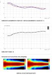
Here are some directivity plots for the FIR settings. No one does this but I have used 1 dB per division !!! Note how well the mid behaves and that the nominal response is better than +/- 0.5 dB with 1/3 Oct smoothing.

The first picture is the vertical plot, the second is the horizontal plot, the third is 18sound plots http://www.eighteensound.it/Portals/0/PDFs/XT1464.PDF

As you can see the 18sound horn is very well behaved when you look at it "normally" ... so be careful when looking at the 1 dB plots. Even where the response looks awful, above 1KHz its still +/- 3 dB. Also notice how well behaved the phase response is on and off axis.

I'm still going to try a few more tricks tomorrow to see if I can improve the directivity transition between the VHF and HF.

I have also posted my HF and VHF IIR settings.

MID crossover 24dB LR - 600Hz
HF Crossover 24dB Butterworth - 6K5Hz

MID

polarity +ve
delay 0ms

HF

polarity +ve
delay 1.54ms

VHF

Polarity -ve
delay 1.76ms
 

Attachments

  • 60 degree directivity 2.jpg
    60 degree directivity 2.jpg
    437 KB · Views: 130
  • 60 degree Horizontal 2.jpg
    60 degree Horizontal 2.jpg
    427 KB · Views: 136
  • hf.jpg
    hf.jpg
    232.6 KB · Views: 129
  • vhf.jpg
    vhf.jpg
    222.4 KB · Views: 113
  • 18sound directivity.jpg
    18sound directivity.jpg
    86.4 KB · Views: 118
Last edited:
Re: 60 Degree DIY Mid Hi

As usual, great work Peter :)

I'm looking at this project from a stacking point, I have a marked for a stackable, compact high output system and no riders to worry about.
My idea is to build four high output subwoofers and four high output top boxes that focuses on sound quality and ease of use. No angles, rigging etc., just point the loud part at the audience and go. My target is audiences ranging from 250-750 outdoors :)


Sent from my iPhone
 
Re: 60 Degree DIY Mid Hi

Here are some directivity plots for the FIR settings. No one does this but I have used 1 dB per division !!! Note how well the mid behaves and that the nominal response is better than +/- 0.5 dB with 1/3 Oct smoothing.

The first picture is the vertical plot, the second is the horizontal plot, the third is 18sound plots http://www.eighteensound.it/Portals/0/PDFs/XT1464.PDF

As you can see the 18sound horn is very well behaved when you look at it "normally" ... so be careful when looking at the 1 dB plots. Even where the response looks awful, above 1KHz its still +/- 3 dB. Also notice how well behaved the phase response is on and off axis.

I'm still going to try a few more tricks tomorrow to see if I can improve the directivity transition between the VHF and HF.

I have also posted my HF and VHF IIR settings.

MID crossover 24dB LR - 600Hz
HF Crossover 24dB Butterworth - 6K5Hz

MID

polarity +ve
delay 0ms

HF

polarity +ve
delay 1.54ms

VHF

Polarity -ve
delay 1.76ms

Peter, Many thx ! Settings sound truly excellent. I'm using Qsc's pld 4 channel DSP on a single box...seems to working very well for the IIR.
I take it the red -5 for HF, and -6 for VHF are the gains. I hope so.... I set it up without the gain reductions and thought I had to be doing something wrong ....needed sunglasses to listen :blush:

BTW, I got the 90 degree version running with your previous settings. It too is singing! Slightly laid back from the 60 degree...but in a pleasant slightly warmer way....I guess that has a lot to do with the dispersion too. What a difference in horiz coverage
I do get the feeling the 90 degree is a great powerful all round box, and the 60 degree is, well .... let's crank! Both are so very clean sounding..
 
Re: 60 Degree DIY Mid Hi

1. I'm thinking 15 deg? None of the more popular ground stack boxes are more than 22.5 deg on the edge. The front is already 15" with a full length grille. The reason I might not even bother is because of number 2.
2. I meant the internal baffles. The interior angles are very, very strange when the sides of the box are angled, and they are not parallel to the other side of the pieces (because they are trapezoids).

Honestly, I don't see how it would be worth doing, or even possible, without a very, very large amount of effort and complicated parts. However, it would make the product truly beyond anything else currently in production for the weight, form factor, and output.

Thx Max, now I see what you meant. Almost need a compound-compound sliding miter saw haha. I use an Incra sliding miter table on my table saw and love it....but I still can't picture how to make the baffle board cut you're describing.
Like you it seems, I've enjoyed building the box nearly as much as the audio. I don't have access or knowledge to pursue CNC.
But one tool I got for this project has exponentially raised my ability to made good cuts....a plunge/track saw. So help me, I can make truer cuts with it that I can with my table saw...and I grew up on a table saw.
 
Re: 60 Degree DIY Mid Hi

As usual, great work Peter :)

I'm looking at this project from a stacking point, I have a marked for a stackable, compact high output system and no riders to worry about.
My idea is to build four high output subwoofers and four high output top boxes that focuses on sound quality and ease of use. No angles, rigging etc., just point the loud part at the audience and go. My target is audiences ranging from 250-750 outdoors :)
same here! on subs 'll give the 18sound plan ( https://soundforums.net/threads/11199-No-compromises-front-loaded-double-18"-cab , post#8) a try... 8)~:cool:~:cool:
 
Re: 60 Degree DIY Mid Hi

Peter, Many thx ! Settings sound truly excellent. I'm using Qsc's pld 4 channel DSP on a single box...seems to working very well for the IIR.
I take it the red -5 for HF, and -6 for VHF are the gains. I hope so.... I set it up without the gain reductions and thought I had to be doing something wrong ....needed sunglasses to listen :blush:

BTW, I got the 90 degree version running with your previous settings. It too is singing! Slightly laid back from the 60 degree...but in a pleasant slightly warmer way....I guess that has a lot to do with the dispersion too. What a difference in horiz coverage
I do get the feeling the 90 degree is a great powerful all round box, and the 60 degree is, well .... let's crank! Both are so very clean sounding..

No ... they are the output socket numbers (1,2,3,4,5,6 L,M,H, L,M,H). Sorry I forgot the gains - the VHF and HF are the same. The mid to HF/VHF - you will have to take your best guess as I have not done any settings with the RCF drivers and the 60 degree horn.

We are both using slightly different processors, so I suspect there will be some variation from what I have done to what you are getting out of the QSC ... obviously they are not too far apart, but you may need to tweak things a little.

.... and yes the 90 degree box is great for most applications. The 60 degree box will be great in pairs or where you need a narrow pattern box to minimize wall reflections etc.

With your construction method if you find a better horn flare you can change it over.

I'm so pleased you guys are getting some great results :)~:)~:smile:
 
Last edited:
Re: 60 Degree DIY Mid Hi

No ... they are the output socket numbers (1,2,3,4,5,6 L,M,H, L,M,H). Sorry I forgot the gains - the VHF and HF are the same. The mid to HF/VHF - you will have to take your best guess as I have not done any settings with the RCF drivers and the 60 degree horn.

We are both using slightly different processors, so I suspect there will be some variation from what I have done to what you are getting out of the QSC ... obviously they are not too far apart, but you may need to tweak things a little.

.... and yes the 90 degree box is great for most applications. The 60 degree box will be great in pairs or where you need a narrow pattern box to minimize wall reflections etc.

With your construction method if you find a better horn flare you can change it over.

I'm so pleased you guys are getting some great results :)~:)~:smile:

Funny ! But hey, those socket numbers did a nice job balancing the overall MF to HF/VHF :D~:-D~:grin:

One horn puzzler I've been meaning to ask....
I've been under the impression the width/heigth of the horn mouth controls both the dispersion pattern, and the freq pattern control extends down to...
And that the longer the horn mouth dimension, the narrower the dispersion, and the lower the freq control extends to...

So these impressions make me wonder why the XT1460 as mounted in the DIY, horizontally wider than taller, has wider horiz than vertical coverage?
Don't mean to ask you such basic stuff if there isn't a quick answer....any recommended primer material?

You deserve to be pleased ! the results are really yours !!
 
  • Like
Reactions: David Westom
Re: 60 Degree DIY Mid Hi

One horn puzzler I've been meaning to ask....
I've been under the impression the width/heigth of the horn mouth controls both the dispersion pattern, and the freq pattern control extends down to...
And that the longer the horn mouth dimension, the narrower the dispersion, and the lower the freq control extends to...

!
Here are the "basics" regarding pattern control etc.

If 2 horns have the same physical horn exit, the one with the wider pattern will control down lower. Or put another way, if you want to have pattern control to a given freq, the narrower pattern horn will have to be LARGER than the wider pattern horn.

With a given mouth size, the narrower pattern horn will be deeper than the wider pattern horn.

Here is the "basic" formula. Freq of control=1,000,000/(pattern of horn in degrees x size of opening in inches).

Of course metric would be different. 2.54 cm=1inch.
 
Re: 60 Degree DIY Mid Hi

Funny ! But hey, those socket numbers did a nice job balancing the overall MF to HF/VHF :D~:-D~:grin:

One horn puzzler I've been meaning to ask....
I've been under the impression the width/heigth of the horn mouth controls both the dispersion pattern, and the freq pattern control extends down to...
And that the longer the horn mouth dimension, the narrower the dispersion, and the lower the freq control extends to...

So these impressions make me wonder why the XT1460 as mounted in the DIY, horizontally wider than taller, has wider horiz than vertical coverage?
Don't mean to ask you such basic stuff if there isn't a quick answer....any recommended primer material?

You deserve to be pleased ! the results are really yours !!

Here is my attempt at a simple explanation -

When the size of the horn is large compared to the wave lengths involved the angle of the horn walls controls the pattern.

When the wave lengths become larger the dimensions of the horn mouth become important. The smallest dimension will lose pattern control first. In the case of the XT1464 it’s wider than it is high and the vertical pattern starts to becomes wider than the horizontal pattern at about 1.7KHz. - see the plots in my above post.

If you don’t want this to happen then the horn has to higher than it is wide; but that’s tricky. To do that you need to make the horn more like the RCF950 where you have a long throat that exits in a narrow tall slot into the main part of the flare. The problem with that approach is that the long throat with this type of shape is not as nice acoustically as the nice smooth expansion of the XT1464.

With the DIY it’s the same width as the HF horn, so the transition between HF and LF horn works almost perfectly in the horizontal plan. Vertically the two LF exits form a dipole controlling the vertical pattern. By selecting the appropriate crossover frequency and the physical dimensions of the HF and MID sections, the two sections blend to achieve reasonably good vertical pattern control, much better that your normal 15” + separate horn for example.

FWIW I did my best to model this before I built the prototype.
The end result is that the DIY, compared to most speakers of a similar size has an excellent pattern control, both horizontal and vertical.
 
Last edited:
Re: 60 Degree DIY Mid Hi

Here are the "basics" regarding pattern control etc.

If 2 horns have the same physical horn exit, the one with the wider pattern will control down lower. Or put another way, if you want to have pattern control to a given freq, the narrower pattern horn will have to be LARGER than the wider pattern horn.

With a given mouth size, the narrower pattern horn will be deeper than the wider pattern horn.

Here is the "basic" formula. Freq of control=1,000,000/(pattern of horn in degrees x size of opening in inches).

Of course metric would be different. 2.54 cm=1inch.

Thx Ivan, that formula seems to give higher freq's than I expected, given the impressions I've gotten over the years reading specs. But I've found so many of my impressions to be nearly as bad as the specs lol :?~:-?~:???:
What drop in response is implicit in that "basic formula? -6db?
 
Re: 60 Degree DIY Mid Hi


Here is my attempt at a simple explanation -

When the size of the horn is large compared to the wave lengths involved the angle of the horn walls controls the pattern.

When the wave lengths become larger the dimensions of the horn mouth become important. The smallest dimension will lose pattern control first. In the case of the XT1464 it’s wider than it is high and the vertical pattern starts to becomes wider than the horizontal pattern at about 1.7KHz. - see the plots in my above post.

If you don’t want this to happen then the horn has to higher than it is wide; but that’s tricky. To do that you need to make the horn more like the RCF950 where you have a long throat that exits in a narrow tall slot into the main part of the flare. The problem with that approach is that the long throat with this type of shape is not as nice acoustically as the nice smooth expansion of the XT1464.

With the DIY it’s the same width as the HF horn, so the transition between HF and LF horn works almost perfectly in the horizontal plan. Vertically the two LF exits form a dipole controlling the vertical pattern. By selecting the appropriate crossover frequency and the physical dimensions of the HF and MID sections, the two sections blend to achieve reasonably good vertical pattern control, much better that your normal 15” + separate horn for example.

FWIW I did my best to model this before I built the prototype.
The end result is that the DIY, compared to most speakers of a similar size has an excellent pattern control, both horizontal and vertical.

Thanks Peter, it's clear I need to develop an intuitive sense for actual wavelengths. I'll be thinking about all this as I do Smaart school this week...

Switching gears, I have a single 60 deg DIY pointing out over the lake right now....just went out on the dock and measured 103-104 dbC slow, ratshack meter. 150-160ft. 2 orbit shifter subs.
Very clean at that level. All my kids and their friends grinning. Subs were short of power with a bridged plx 3402 on each. I think 4 properly powered OS's or labsubs, per DIY would be a nice match.
 
Re: 60 Degree DIY Mid Hi

Thanks Peter, it's clear I need to develop an intuitive sense for actual wavelengths. I'll be thinking about all this as I do Smaart school this week...

Switching gears, I have a single 60 deg DIY pointing out over the lake right now....just went out on the dock and measured 103-104 dbC slow, ratshack meter. 150-160ft. 2 orbit shifter subs.
Very clean at that level. All my kids and their friends grinning. Subs were short of power with a bridged plx 3402 on each. I think 4 properly powered OS's or labsubs, per DIY would be a nice match.

Here is a bit more information -

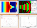
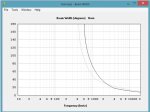
Below are some plots for the DIY mid horn from HornResp. It assumes a round horn, which the DIY is not, however you can play around with your input parameters and it will give you some idea.

Previously with the help of a friend I have used a proprietary Finite Element Analysis based program to achieve better predictions, it takes a lot of time but the results were similar to HornResp, so for the DIY I just use HornResp and a few other tricks and guesses.

The second plot compares the directivity of two horns with the same size mouth. Other than one horn being half the length of the other they are exactly the same, of course the exit angles are greater for the shorter horn. The short horn is the dark trace.
 

Attachments

  • directivity sims.jpg
    directivity sims.jpg
    326 KB · Views: 74
  • directivity 2.jpg
    directivity 2.jpg
    79.9 KB · Views: 73
Last edited:
Re: 60 Degree DIY Mid Hi

Peter,
A question for you, now that you have your boxes completed, how to plan on transporting and protecting them? Custom covers? Caster boards?
I've been giving this some thought and don't have a clear direction yet. Mine are a little awkward to carry now that the grills are on them.


Not sure; I will probably make some covers – 2 fit perfectly on my mic-stand case, so I may use that as the caster board.

I’m just waiting on some new grills to finish off the 60degree boxes, then I will cut the back corners of the 90 degree prototypes and tidy up the box a little … then it’s the dual 21 inch sub to match.


I’m also in the process of building some flying hardware / frames etc.
 
Re: 60 Degree DIY Mid Hi

Thx Ivan, that formula seems to give higher freq's than I expected, given the impressions I've gotten over the years reading specs. But I've found so many of my impressions to be nearly as bad as the specs lol :?~:-?~:???:
What drop in response is implicit in that "basic formula? -6db?
It is not the freq response, but rather the freq at which the horn will have "control" (the rated pattern) over the sound.

As you go lower in freq the pattern gets wider.

Of course this is not a "stopping point"-but rather a "sliding scale" and a rough approximation of the control/freq

There are other things that affect the overall final result. Things like the flare break etc will affect the final results and what "happens" around the cutoff freq.
 
Re: 60 Degree DIY Mid Hi

It is not the freq response, but rather the freq at which the horn will have "control" (the rated pattern) over the sound.

As you go lower in freq the pattern gets wider.

Of course this is not a "stopping point"-but rather a "sliding scale" and a rough approximation of the control/freq

There are other things that affect the overall final result. Things like the flare break etc will affect the final results and what "happens" around the cutoff freq.


Yes, I understood you were talking about freq of control, sorry if i didn't convey that in my last post....

In the rule of thumb formula, 10^6 / (degrees x inches )..... what is inches? cone diameter? horn width/ height? box width / height? array width / height? (assuming they array well)
Just trying to get a sense of how to intuitively apply the rule...

BTW, thx for the encouragement a few months back to attend smaart class. Just finished a 3 day that was well worth it. Learned alot, and learned a whole lot more questions !!! :eek:~:-o~:eek:
 
Re: 60 Degree DIY Mid Hi

Yes, I understood you were talking about freq of control, sorry if i didn't convey that in my last post....

In the rule of thumb formula, 10^6 / (degrees x inches )..... what is inches? cone diameter? horn width/ height? box width / height? array width / height? (assuming they array well)
Just trying to get a sense of how to intuitively apply the rule...

BTW, thx for the encouragement a few months back to attend smaart class. Just finished a 3 day that was well worth it. Learned alot, and learned a whole lot more questions !!! :eek:~:-o~:eek:

10,000,000 / (60 degrees x 15”) = 1111 Hz ... where the 60 degree XT1464 will start to loose horizontal pattern control. 10,000,000 / (50 degrees x 12”) = 1666 Hz – vertical pattern control

If you have a look at the directivity plots for the XT1464, that’s about right. Blue and red line in my above post.
 
Re: 60 Degree DIY Mid Hi

Here is a bit more information -

Below are some plots for the DIY mid horn from HornResp. It assumes a round horn, which the DIY is not, however you can play around with your input parameters and it will give you some idea.

Previously with the help of a friend I have used a proprietary Finite Element Analysis based program to achieve better predictions, it takes a lot of time but the results were similar to HornResp, so for the DIY I just use HornResp and a few other tricks and guesses.

The second plot compares the directivity of two horns with the same size mouth. Other than one horn being half the length of the other they are exactly the same, of course the exit angles are greater for the shorter horn. The short horn is the dark trace.

Thanks for those two explaining posts. They are slowly beginning to make some sense....especially as I read back over previous posts where you describe modeling and design decisions...

In thinking about building some more 60 DIY boxes.... I'd love to get the XT1464 all the way inside the walls. Does that necessary extra width matter as far the way the slot under the 12" expands into the beginning of the MF horn?
I'm thinking not much really,..... partly because I see it's ok to lop the corners off the box, the way you're doing.
I mean, doesn't the corner "lop off" make for a slight restriction?....which evidently doesn't matter...? So maybe things about the MF horn aren't so critical....
Maybe the right question is what dimensions or flare particulars are critical?

And I know you left your 60 degrees the full depth you had available without cutting any off. That would appear to give some help to directivity per your above post.
Did you keep the depth for that? , or to keep your box looking as good as it does !