
Re: FIR filters

If I feed it an impulse it makes a nice symmetrical arrowhead. But I better go back and take a careful look at my code to see what it's really doing.
The purpose of the initial window is just decisively to chop off the acoustic reflections to ensure an anechoic measurement. As in 2 times a 13 ft high tower minus 10 ft from speaker to mic = 16 ft. or 14 ms. But I think you're right in that any reflection should show up at its time in the TFE representation and the initial window is unnecessary. I should take a measurement holding a road case cover a few feet from the central axis and see what it looks like. I'll try turning off the initial window on the data I have and see if I can see the ground bounce out at ~15 ms.
--Frank
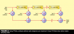
I see a double sided time response like this:I suspect the initial window might be redundant
If I feed it an impulse it makes a nice symmetrical arrowhead. But I better go back and take a careful look at my code to see what it's really doing.
The purpose of the initial window is just decisively to chop off the acoustic reflections to ensure an anechoic measurement. As in 2 times a 13 ft high tower minus 10 ft from speaker to mic = 16 ft. or 14 ms. But I think you're right in that any reflection should show up at its time in the TFE representation and the initial window is unnecessary. I should take a measurement holding a road case cover a few feet from the central axis and see what it looks like. I'll try turning off the initial window on the data I have and see if I can see the ground bounce out at ~15 ms.
--Frank


")