Re: New DIY Mid High
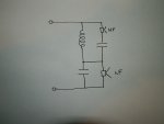
The crossover is tricky in this case - I think (I may be wrong) from the quick look I had, its a series derived passive crossover and is connected as shown below.
If you ignore the low driver in the circuit the VHF has an 18dB crossover, and if you ignore the VHF the HF driver has a 12dB crossover.
Soooo I think it will not be a standard filter shape / slope and it will have an ultimate slope of 12 & 18 dB.
On a related note, the link from Peter states an asymmetrical slope, 12 and 18 db/octave.
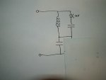
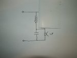
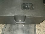
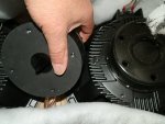
But I question this. There are three components, as seen in the pictures. Two caps, and one inductor.
It is my understanding that one cap would be 6 db/octave, and one cap one inductor would be 12 db/octave. Comments?
The crossover is tricky in this case - I think (I may be wrong) from the quick look I had, its a series derived passive crossover and is connected as shown below.
If you ignore the low driver in the circuit the VHF has an 18dB crossover, and if you ignore the VHF the HF driver has a 12dB crossover.
Soooo I think it will not be a standard filter shape / slope and it will have an ultimate slope of 12 & 18 dB.

