60 Degree DIY Mid Hi - AKA PM60

Re: 60 Degree DIY Mid Hi

Thanks Peter, I've been installing those inserts backwards all these years and Timo for the idea.
I've come up with an idea I may try on my build that will eliminate the 10mm spacer under the 12's.
If you use 17mm ply for the baffle you can route about 8mm out of the shape of the driver cut out. This leaves a 9mm thick panel.
The xmax for the driver is 5.5 so even if xlim is 25% greater it shouldn't hit the face.
This would hopefully allow for more room for the fit with XT1464 combo. Just a thought.
Xmax is NOT the maximum travel a cone can have. It can have different meanings (derived different ways). Sometimes it is calculated-other times it is measured in the form of distortion.

Basically what it means is NOT the maximum travel-but the maximum travel while staying clean and linear.

OF course many PA systems are operated well beyond "linear".

But in "normal usage" a cone can move quite a bit more than the rated "xmax".

When the cone hits the wood-you get a real loud "crack" or snapping sound.

You might want to consider clearances closer to "xdamage" to ensure good clearance.
 
Re: 60 Degree DIY Mid Hi

Xmax is NOT the maximum travel a cone can have. It can have different meanings (derived different ways). Sometimes it is calculated-other times it is measured in the form of distortion.

Basically what it means is NOT the maximum travel-but the maximum travel while staying clean and linear.

OF course many PA systems are operated well beyond "linear".

But in "normal usage" a cone can move quite a bit more than the rated "xmax".

When the cone hits the wood-you get a real loud "crack" or snapping sound.

You might want to consider clearances closer to "xdamage" to ensure good clearance.
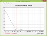
You are absolutely correct Ivan. I estimated that the I had 10mm from the spacer + about 1mm from the cone offset relative to the frame, plus an additional 2 mm as a result of the suspension flattening as it near its extreme limit.

i.e. it could withstand about 13mm of cone travel before it hit the front plate with a 10mm spacer. That corresponds to 2600 watts input per driver at 100Hz – the nominal crossover point.


I also looked at the sensitivity to changing the volume between the speaker cone and the horn mouth, and the effect it had on the frequency response.


Here is a plot of the cone excursion at 1300 watts per driver, the nominal program rating of the RCF MB12N351. I think 10mm is about right but I figured if I have problems I could add a small spacer. I also assumed at these types of drive levels (2600W) that some dynamic limiting will occur and it would be difficult for a driver with a VC length of 16.5mm and a top plate thickness 11mm to achieve the calculated Xmax.


Attachments

  • X max.jpg
    X max.jpg
    85 KB · Views: 95
Last edited:
Re: 60 Degree DIY Mid Hi

You might want to consider clearances closer to "xdamage" to ensure good clearance.

Thanks Ivan, do manufacturers provide xdamage specs or does this need to be calculated?
One of the first DIY projects I ever did was a pair of 15" front loaded subs. I installed nice grills then took them out to an event. I didn't realize the grill was too close and heard the noise you describing.
 
Re: 60 Degree DIY Mid Hi

Hi Peter,
Good to see you took the plunge on Sketchup too. Not that bad once you get into it.
So I'll shoot for a minimum of 10mm clearance instead of 8 to maintain the cone volume offset and a safe clearance for the excursion. Doubtful I'll ever be able to drive these at 1300 watts each in our applications.
 
Re: 60 Degree DIY Mid Hi

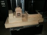
Here's a model if it helps.
Baffles boards and the RCF MB12N351's are set up per Don's drawings.
The wood disc is 133mm dia, matching the 4594 (i'm assuming HE has same spec?). The disc is setting on the frames of the RCF MB12N351's, so it is as low as it can go.

You can see the edge of the disc is about 8-9mm from the cone. (The disc is 18mm thick)

Here's the total cabinet inside depth this represents from the XT1464 flange...if I did the math right.
The XT1464 flange to flange is 243mm. The 4594 is 79mm, for a total assembly of 322mm
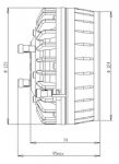
See 4594 drawing below. Does it use an gasket ?
The depth of the bottom of the disc as pictured, from the inside back wall would be 85mm. This is with the 10mm 12" spacer.
This gives a total inside depth of 322 + 85 = 407mm... ......for the 8-9mm clearance shown.

How much does the clearance need to be? You guys are figuring that !

But say we add a generous? 10mm....
That would give a total XT1464 flange to back inside-wall depth of 417mm.
Add 17mm for back wall thickness, and 15mm for the plan's front setback of the XT,
for a total cabinet depth of 449mm.

To me, it appears the plans 455mm work, with room to chisel a little...
depth 1.jpgdepth 2.jpg4594.JPG
 
Re: 60 Degree DIY Mid Hi

Here's a model if it helps.
Baffles boards and the RCF MB12N351's are set up per Don's drawings.
The wood disc is 133mm dia, matching the 4594 (i'm assuming HE has same spec?). The disc is setting on the frames of the RCF MB12N351's, so it is as low as it can go.

You can see the edge of the disc is about 8-9mm from the cone. (The disc is 18mm thick)

Here's the total cabinet inside depth this represents from the XT1464 flange...if I did the math right.
The XT1464 flange to flange is 243mm. The
4594 is 79mm, for a total assembly of 322mm
See 4594 drawing below. Does it use an gasket ?
The depth of the bottom of the disc as pictured, from the inside back wall would be 85mm. This is with the 10mm 12" spacer.
This gives a total inside depth of 322 + 85 = 407mm... ......for the 8-9mm clearance shown.

How much does the clearance need to be? You guys are figuring that !

But say we add a generous? 10mm....
That would give a total XT1464 flange to back inside-wall depth of 417mm.
Add 17mm for back wall thickness, and 15mm for the plan's front setback of the XT,
for a total cabinet depth of 449mm.

To me, it appears the plans 455mm work, with room to chisel a little...
View attachment 12367View attachment 12368View attachment 12369


You have to allow for the terminals 79 mm + 16 mm = about 95mm .... that gives a total depth of 455mm :)~:-)~:smile:
 
Last edited:
Re: 60 Degree DIY Mid Hi

You have to allow for the terminals 79 mm + 6 mm = about 95mm :-)

Hi Peter, sure you meant 16mm... and yes....

But I measure it's 47mm from the bottom of the 4594 without terminals, to the depth of the vee where the baffle boards meet per picts (47mm is with 10mm spacer included, and if you take the baffle boards all the way together into a vee without part D... some mm less if part D is included) ...
(This is still with just 8-9mm clearance-to-cone per picts.... depth to vee only gets better with more clearance to cone, yes?)

I'm assuming you can rotate the 4594 to put the terminals towards the center of the vee where clearance is deepest, or at least align rotation enough to gain the 16mm clearance needed for terminals?
Is this not possible? Seems like a lot of room for terminals without them being a factor. Maybe I'm still missing something......

You're the only one who really knows...the only one with 4594HE's in hand, in box ! :)

Thx, Mark
 
Re: 60 Degree DIY Mid Hi

Xmax is NOT the maximum travel a cone can have. It can have different meanings (derived different ways). Sometimes it is calculated-other times it is measured in the form of distortion.

Just FYI, we use a calculated Xmax. I always prefer Xvar, which is measured using Klippel and is a much more accurate and consistent measurement of excursion capability.
 
Re: 60 Degree DIY Mid Hi

Peter, need your guidance please :)
below are mock up sides holding an XT1464 in place, with a loaner 4594
The box is per the HF950 plans, so the mock up sides are 430mm deep. I'm using a 12mm spacer between the 12" and baffle boards.
There appears to be pretty good vertical clearance between the 12"s and the 4594, terminals included.

I'd like to keep the box down to 430mm deep, but i know everything you do has a purpose......last I heard you were at 450-455mm deep.
Are there other design considerations apart from clearances, with the increased depth?
Sorry for asking questions away from the posted design...
Many thx, mark

430mm sides.jpg
 
Re: 60 Degree DIY Mid Hi

Peter, need your guidance please :)
below are mock up sides holding an XT1464 in place, with a loaner 4594
The box is per the HF950 plans, so the mock up sides are 430mm deep. I'm using a 12mm spacer between the 12" and baffle boards.
There appears to be pretty good vertical clearance between the 12"s and the 4594, terminals included.

I'd like to keep the box down to 430mm deep, but i know everything you do has a purpose......last I heard you were at 450-455mm deep.
Are there other design considerations apart from clearances, with the increased depth?
Sorry for asking questions away from the posted design...
Many thx, mark

View attachment 12429

Yes ... I have cut the timber at 455 deep, but I was hoping that I can get away with less.

If I can keep it at 430 it would be fantastic and I can cut what I don't need off front edges ... 455 is starting to look a bit big for a stick mounted speaker.

It was just to give me some wriggle room, just in case the terminals of the VHF driver were too close.
 
Re: 60 Degree DIY Mid Hi

Yes ... I have cut the timber at 455 deep, but I was hoping that I can get away with less.

If I can keep it at 430 it would be fantastic and I can cut what I don't need off front edges ... 455 is starting to look a bit big for a stick mounted speaker.

It was just to give me some wriggle room, just in case the terminals of the VHF driver were too close.

Thank you. I'm going to try to stay with 430mm. I'll post if any issues arise....
 
Re: 60 Degree DIY Mid Hi

Thank you. I'm going to try to stay with 430mm. I'll post if any issues arise....

Hi Mark,

I have just noticed that I have about 3-4 mm more space between the back of the speaker box and the speaker mounting plate than shown on the drawings.

It where the 44mm was measured from. I measured it from the outside, the plan has it on the inside. (43.31 mm on the drawing) see below.

The idea was to have the same cross sectional area where the speaker exits into the horn mouth through the 280mm x 75mm slot as there is at the front edge of that 280mm x 75mm slot.

I suspect its not an issue especially if the box is a little wider.
 

Attachments

  • box construction.jpg
    box construction.jpg
    112.6 KB · Views: 371
Re: 60 Degree DIY Mid Hi

Hi Mark,

I have just noticed that I have about 3-4 mm more space between the back of the speaker box and the speaker mounting plate than shown on the drawings.

It where the 44mm was measured from. I measured it from the outside, the plan has it on the inside. (43.31 mm on the drawing) see below.

The idea was to have the same cross sectional area where the speaker exits into the horn mouth through the 280mm x 75mm slot as there is at the front edge of that 280mm x 75mm slot.

I suspect its not an issue especially if the box is a little wider.

Hi Peter, I think i see what you were doing.
I'd better pay attention because i'm trying to hold internal width to 350mm...
(with 2 x 15mm sides for an overall width of 380mm to match XT1464)
Still trying to keep her as small, as light, as possible...this 63 yr old man is a tired old mule !

Does the 78mm between the back of the speaker box and the front edge of the baffle board stay the same? Or does it move out 3-4mm too?
I think i can figure out all the adjustments against the HF950 plans...just need to know where to start ...thx
 
Re: 60 Degree DIY Mid Hi

Hi Peter, I think i see what you were doing.
I'd better pay attention because i'm trying to hold internal width to 350mm...
(with 2 x 15mm sides for an overall width of 380mm to match XT1464)
Still trying to keep her as small, as light, as possible...this 63 yr old man is a tired old mule !

Does the 78mm between the back of the speaker box and the front edge of the baffle board stay the same? Or does it move out 3-4mm too?
I think i can figure out all the adjustments against the HF950 plans...just need to know where to start ...thx

What I’m going to do is add 3mm to the 43.31 and 76mm. I’m using 16mm ply and I’m making it 386mm wide (external). I am planning on eliminating the 10mm space and routing a grove to allow for 10mm of cone travel.

Hopefully that will mean that I can keep the depth to a minimum…. Possibly very close to the original.
 
Re: 60 Degree DIY Mid Hi

What I’m going to do is add 3mm to the 43.31 and 76mm. I’m using 16mm ply and I’m making it 386mm wide (external). I am planning on eliminating the 10mm space and routing a grove to allow for 10mm of cone travel.


Hi Peter, I took your adjustments and went to 47mm and 79mm... this gives a spot-on slope on 9 degrees for the baffle board, and for easier old school calculations :)
Pieces are cut and under glue , yea. (I'm using 18mm BB ply for both horn and 12" baffle boards, as well as MF horn walls. Everything else is 15mm ply.)

So outside dimensions are 380w by 430d by 932h, as I've tried to hold the MF horn dimensions right to 90x50 plan.

Those original plans for the 90x50 are laying out great for both horns...and with removable baffles, double yea.
The HF950 works of course works great as per plans (thank you too, Don) .... the XT1460 baffle board is comprised of a two thickness bafffle board...one spacer the same 18mm thickness as the HT950 baffle, and then 15mm pieces on top of that spacer cut to fit for the XT1464.

Still, a few questions please :)

Is there any reason other than creating clearance between the BMS 4594's terminals and the 12" RCF drivers, to recess the the 12" in the baffle boards?
IOW, does the volume between the driver and baffle board matter?

I've cut 12mm spacers, but have also tooled up to recess the RCF's into the baffle boards per your suggested tiering....doesn't matter construction-wise which way I go...... I think clearance will work either way although that's clearly more certain with recessing ...just want to optimize for sound quality

And what did you find center of gravity, front to back? IOW, pole mount position.

Any reason not to put handles in the center of the box vertically? I'm thinking the handle holes in the center will help making sure wires are OK given the tight clearances.

THANKS