60 Degree DIY Mid Hi - AKA PM60

I have been reading this thread and the 90 degree version thread and have decided to build two 90 degree two way boxes. Thank you Peter Morris for sharing all that knowledge.

What I find most interesting is the DSP things. The tools and methods I see used here are all new to me, but I am looking very much forward to get going.

I have managed to collect all the hardware, so I am ready to make some saw dust.

My wood working skills are limited, so I was hoping that someone would share their experience building the boxes.

First question that pops to my mind is if anyone has built exactly according to Don's (thank you Don) plan: 'diy mid-high 8-6-15a'?

So it would be safe to cut all parts beforehand according to Don's plan? Or do you cut as you go along?

Is there a good method of building? like for example a sequence of assembling the parts, and are you using just glue, or nails or screws?

I have built four Xoc TH-18 tapped horn using screws and normal wood glue on all joints, which I think maybe is not necessary for this build?

I am really looking forward to this project.

Thank you all in advance.
Don's latest pdf is ok. Be very carefull with the space between the drivers: there is very little margin. You could make a mockup to check before you start making sawdust...


If these cabinets will be used on the road, then use glue and screws. 15mm birchply is ok.


I would cut as you go along. This allows to correct a mm if needed. My woodsupplier cut strokes with the same width which I cut into pieces with the right angles. (Tip: If the angle between 2 panels is 10 degrees, you will have to cut both panels at 5 degrees. --> After each cut you can flip the panel and you have the right starting angle for the next panel.)


To simplify the built, I would not route the sidepanels for the inner panels. Just draw where the panels should be on the sidepanels.


Start with the panels for the 12"s. Instead of using spacer rings for the 12"s, I would use 18mm birchply for the panels with the 12"s and route the space for the driver (I did 9mm or so).


Verzonden vanaf mijn iPhone met Tapatalk
 
Thanks a lot Peter van Gils. Your help is very much appreciated.

As I wanted to check where I could share angle cuts I found that my simple school angle-thingie wouldn't give me more than 40 degrees between part A and the horn baffle, and not 50 as the drawing says. Maybe I need more practice :0)

More importantly, It would be very very helpful to have some more measurements on the plan as guideline to newbies as me :0).

I wouldn't have started building without Don's plan so thank you Don, but I think it would be a great help to know the inside measurement from part D to inside of horn baffle and/ or some x y measurements for the panel placement (A B C, 12" baffle and horn baffle).
Would it be possible to extract those measurements directly from the program that was used to make the plan? Please let me know if you think I can help with this.
Andy, I have suffered a PC crash and am sorting out my back ups. Could you either post the plan you are building from or PM me and I'll give you my email address. I can probably clarify your questions on the dimensions fairly easily.
 
Andy, I have suffered a PC crash and am sorting out my back ups. Could you either post the plan you are building from or PM me and I'll give you my email address. I can probably clarify your questions on the dimensions fairly easily.

Okay so long story short I had some of these same questions and ultimately I had to use a parametric CAD system to recreate the exact dimensions of the centerline section showing the baffles. I might be able to answer any of your questions through that as well.
 
Max,
So you guys found yourselves another challenge I see :0) Well I was hoping to meet the first challenges a bit later in the process.

Thank you Max for offering your help. I have PM'ed Don and hope he might be able to extract some of the measurement directly from within the drawing app. Did you build from Don' latest plans(diy mid-high 8-6-15)?

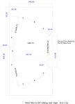
Andy, I've added some dimensions that I think you're looking for. A lot will depend on how accurate your cuts are on the various parts and as Peter Van Gils said cut as you go along. Some adjustments may be necessary. Without shop grade equipment its hard to achieve super accurate cuts. What I did was print the image on page 3 enclosed out full scale on multiple pieces of paper and tape them together as a pattern to lay on the plywood

Hope this helps. diy dbl 12-15mm pg3.jpg
 
Max,
So you guys found yourselves another challenge I see :0) Well I was hoping to meet the first challenges a bit later in the process.

Thank you Max for offering your help. I have PM'ed Don and hope he might be able to extract some of the measurement directly from within the drawing app. Did you build from Don' latest plans(diy mid-high 8-6-15)?

No, actually the design I followed was one of the earlier designs that was posted. From what I am seeing in the newest design posted above, it differs considerably in some areas than the model I went off of - namely in the legth of B/A due to my 60 degree horn baffle being less offset from the front of the box. That said, I could concievably recreate any adjustment to dimensions using my model to ensure that there are no issues with the dimensions presented (the software math is perfect as opposed to normal CAD drawings which can have slight errors that may cause issues further down the line if going the CNC route like I did).
 

Attachments

  • Capture.PNG.jpg
    Capture.PNG.jpg
    129.2 KB · Views: 105
Don, Max.

Thank you very much for sharing. I really appreciate your help a lot.

My main concern is of cause clearance for the CD. Internal volume and horn length I think is not so sensitive.

It seems that the new(60 degree) plans has less distance from Horn baffle to Part D, than Max's version?
If I am reading the plans correctly that is :0)

Max version internal depth: 370.
Don's version internal depth: 345.42. - Would this still be ok for the 90 degree version?

Good idea to put the print directly on the side panel, and just follow the bends/curves, but I was hoping to have enough measurements - x/y for each panel, to draw it instead of printing and attaching. Most important is still the total internal depth though.

Thanks again to both of you :0)

Hi Andy, I've been hesitant to chime in with measurements because I kinda went off on my own to stay as small/light as possible and do interchangeable baffles.....
....but, with only minor differences, I followed Don's earlier 90 degree plan, and the 60 degree fits too. Tight, but it fits !

I just measured and have 342mm internal depth, from the horn baffle to the point where the 12" rests on its baffle board. (This is assuming you are routing out the baffle board for clearance. I used a spacer, so I should really say I have 342mm internal to the spacer.)

Real bottom line IMO is, you have boat loads of front-to-back clearance for the 90 degree at 342mm...

FWIW, I bought a big sketch pad and laid out the design full size, old school trig style, and was sure enough of dimensions I just pre-cut everything, and all worked well.

Hi Mark,

Thank you very much for your input.
 
Last edited:
Hi Mark,

Thank you very much for your input.

So I reckon you measured the 342mm as close to the center of the cabinet as possible?

I wonder why the internal width was increased from 346mm in 'diy dbl 12.v1.md60' to 356mm in the latest plan 'diy mid-high 8-6-15a'?

Hi Andy, glad to pass on some help like has been so generously given to me !

I measured 342mm to the mounting surface of the 12" driver. I didn't measure to the center because I ran the 12" babble boards together without making a Part D, so my center measurement would be misleading.

The increased internal width is just because the 60 degree horn requires it, no other reason I know of....
 
Hi again Mark,

Was this the plan you followed? With 430mm external width and 385mm - (2x17mm plywood) deep? And this should be ok for the 60 degree horn also?


Sorry for all the questions :0)

Hi again Andy

I used the 'diy dbl 12.v1.md60' plan,
This plan should work great for the 90 degree. I would NOT expect it to work with the 60 degree unless you spend alot of time drafting/modeling ......knowing it will.

My convertible box ended up 430mm external depth, and 380mm external width....( t think you accidentally went backwards above)

FWIW, I would not make a convertible box again, way too much detail and custom mounting crap necessary,...
and again in the case of basing it off of 90 degree plans...too tight with the 60 degree horn for any error .
I'm leaving my boxes in the 90 degree config, and beginning to build a new pair of 60's.
I'm going to make the 60 degrees wide enough to accommodate the 60 degree horn inside the side walls.

I guess what I'm really trying to recommend is if you want the 90, the 90 plans should work great.
 
Here's a pict of the 90 deg in my box....as you can see, there is plenty of front-to-back clearance between 12" cone and BMS.
The tight part is the frame to frame clearance between the two 12" and the BMS, .....which is controlled by cabinet height, and 12" baffle board spacing/angle.
Oh, I should add...12" is rcf...might be a little difference clearance with B&C ?????? 90 deg clearance resize.jpg


Hi Mark,

Ok, so your explanations convinced me to do the same as you, - build specifically for the 90 or 60 degree horn. I prefer having a straight front baffle with grill and foam.

Settling for the 'diy dbl 12.v1.md60' plan while building the 90 degree version, I could opt for making it less than 380 wide? Or do you recommend leaving it at 380 to maintain internal volume? I was trying to find the width for the 90 degree plan, - the one enclosed in my post 593, but had no luck.

I have the rcf's also :0)

Thank you for the picture. I can see that you really need to think as you go along with the assembling. It looks as if the width between the 12s is actually more of an issue then the depth? If I stick to the 'diy dbl 12.v1.md60' plan and keep part D, then maybe this is going to be less of a potential issue.

Thanks.

Glad to be able to help :)

I think you are looking for Don's plan in post #316 in the New DIY Mid High thread.

Yes, the distance between the 12"s is the critical distance....
If you omit part D, you have to extend the 12" baffles to make up the distance, so there is no change in spacing between the 12"s....so the only real change is eliminating a part (which some folks like)
 
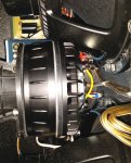
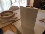
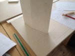
Getting started. I will put one 12" baffle with driver and the horn baffle also with horn and driver to check if there will be enough space. I am building from the 'diy dbl12.v1.md60' plans but changed from 17 to 15mm.
 

Attachments

  • Fil_001.jpeg
    Fil_001.jpeg
    202.2 KB · Views: 62
  • Fil_000.jpeg
    Fil_000.jpeg
    167.5 KB · Views: 62
  • Like
Reactions: Sammy boeren